
Fixing device and image forming apparatus including same

a technology of fixing device and image forming apparatus, which is applied in the direction of electrographic process apparatus, instruments, optics, etc., can solve the problems of limited range of adjustment of heating width and overheating

Inactive Publication Date: 2011-08-18
RICOH KK
View PDF7 Cites 99 Cited by
  • Summary
  • Abstract
  • Description
  • Claims
  • Application Information

AI Technical Summary

Problems solved by technology

In such a case, a portion of the fixing member, for example, end portions in the axial direction, which does not contact the recording medium, remains heated by the heating member, thereby getting overheated because there is no recording medium to draw heat from the fixing member at that portion.
Although advantageous, a range of adjustment of the heating width is limited to the number of heat sources employed in the heating roller.

Method used


Image

  • Fixing device and image forming apparatus including same
  • Fixing device and image forming apparatus including same
  • Fixing device and image forming apparatus including same

Examples


Embodiment Construction

[0035]A description is now given of exemplary embodiments of the present invention. It should be noted that although such terms as first, second, etc. may be used herein to describe various elements, components, regions, layers and / or sections, it should be understood that such elements, components, regions, layers and / or sections are not limited thereby because such terms are relative, that is, used only to distinguish one element, component, region, layer or section from another region, layer or section. Thus, for example, a first element, component, region, layer or section discussed below could be termed a second element, component, region, layer or section without departing from the teachings of the present invention.

[0036]In addition, it should be noted that the terminology used herein is for the purpose of describing particular embodiments only and is not intended to be limiting of the present invention. Thus, for example, as used herein, the singular forms “a”, “an” and “the...


PUM


Abstract

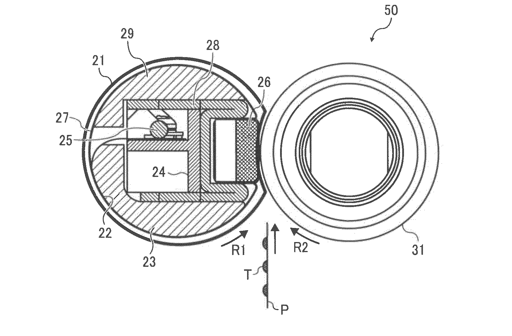
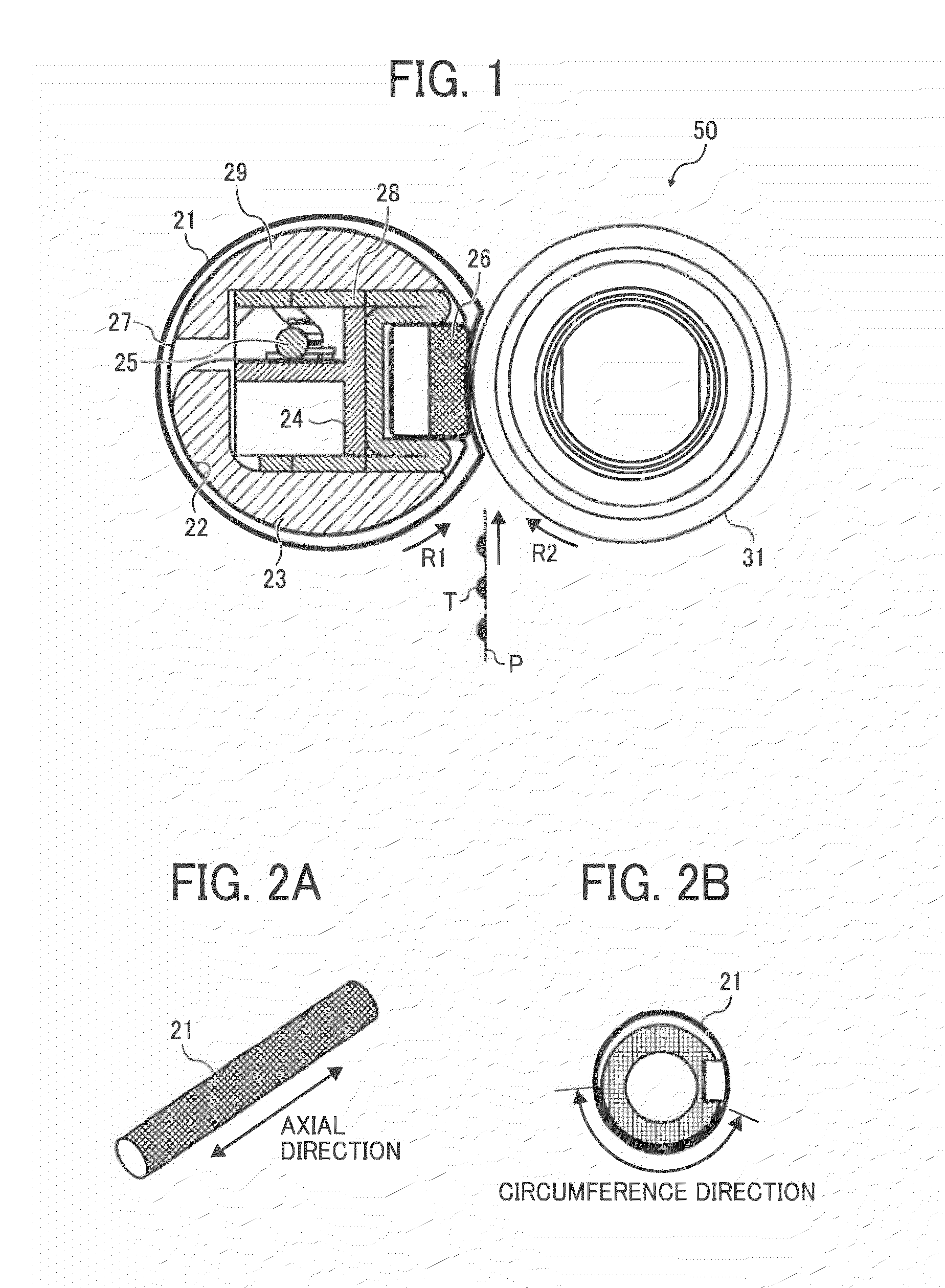
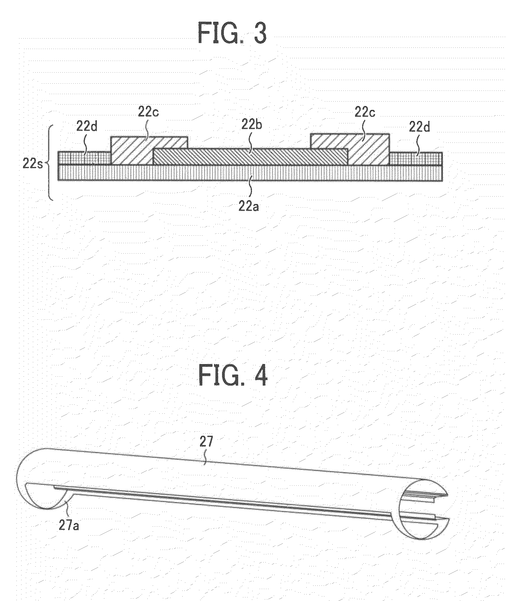
A fixing device includes a contact member provided inside a fixing member and pressed against a pressing member via the fixing member to form a nip between the pressing member and the fixing member through which a recording medium bearing atoner image passes. A sheet heat generator provided in the fixing member includes a flexible heat generation sheet contactable against the fixing member to heat the fixing member. A contact adjuster provided in the fixing member adjusts an area of contact of the heat generation sheet and the fixing member in the axial direction, supports the heat generation sheet at a first position at which the heat generation sheet contacts the fixing member, and bends a portion of the heat generation sheet at a second position to separate the heat generation sheet from the fixing member.

Description

CROSS-REFERENCE TO RELATED APPLICATIONS[0001]The present application is based on and claims priority to Japanese Patent Application No. 2010-028912, filed on Feb. 12, 2010 in the Japan Patent Office, which is hereby incorporated herein by reference in its entirety.BACKGROUND OF THE INVENTION[0002]1. Field of the Invention[0003]Exemplary aspects of the present invention relate to a fixing device and an image forming apparatus, and more particularly, to a fixing device for fixing a toner image on a recording medium, and an image forming apparatus including the fixing device.[0004]2. Description of the Related Art[0005]Related-art image forming apparatuses, such as copiers, facsimile machines, printers, or multifunction printers having at least one of copying, printing, scanning, and facsimile functions, typically form an image on a recording medium according to image data. Thus, for example, a charging device uniformly charges a surface of an image carrier; an optical writer emits a l...

Claims


Application Information

Patent Timeline
IPC IPC(8): G03G15/20
CPCG03G15/2064G03G15/2032G03G2215/2035
Inventor YAMAGUCHI, YOSHIKIYOSHIKAWA, MASAAKIISHII, KENJIIWAYA, NAOKITOKUDA, TETSUOIKEBUCHI, YUTAKAIMADA, TAKAHIROHASE, TAKAMASASHIMOKAWA, TOSHIHIKOYOSHINAGA, HIROSHIFUJIMOTO, IPPEI
Owner RICOH KK
Learn More