Motion compensated interpolation system using combination of full and intermediate frame occlusion

Active Publication Date: 2011-09-01
STMICROELECTRONICS SRL
View PDF7 Cites 14 Cited by
  • Summary
  • Abstract
  • Description
  • Claims
  • Application Information

AI Technical Summary

Problems solved by technology

Traditionally, motion compensation algorithms such as the one described above suffer from problems with respect to occlusions.
Judder problems with modern displays, however, have been becoming

Method used


Image

  • Motion compensated interpolation system using combination of full and intermediate frame occlusion
  • Motion compensated interpolation system using combination of full and intermediate frame occlusion
  • Motion compensated interpolation system using combination of full and intermediate frame occlusion

Examples


first embodiment

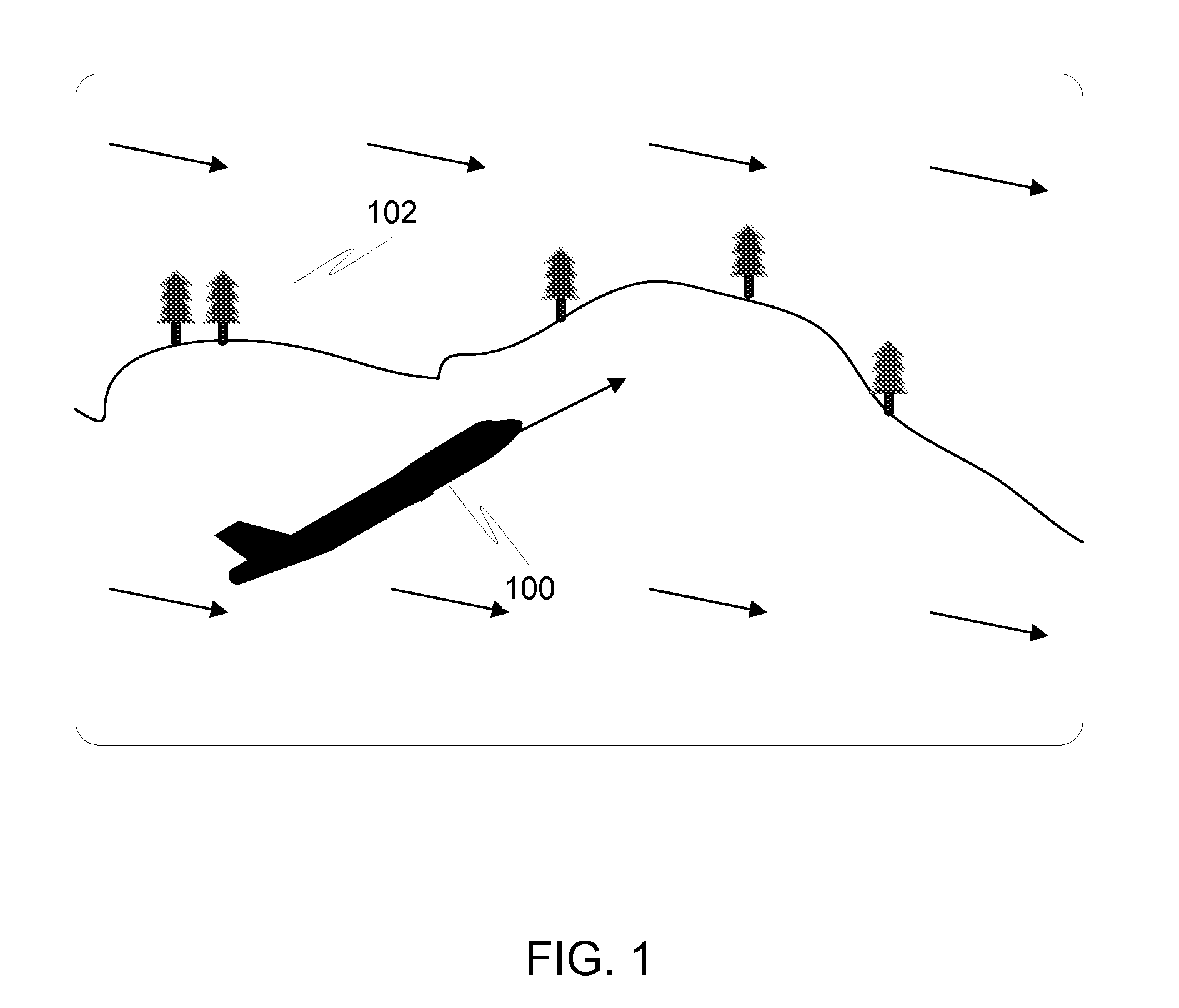
[0050]In the present invention, special care is taken to detect occlusion areas of a display as they are occurring. Specifically, the system looks for conceal areas and reveal areas. A conceal area is one where a motion compensated pixel in the previous frame does not have a corresponding match in the current frame, meaning that a moving object has covered up the pixel in the most recent frame. A reveal area is one where a motion compensated pixel in the current frame does not have a corresponding match in the previous frame, meaning that a moving object has moved away from an area of the background, revealing the background underneath. Both conceal and reveal areas are occlusion areas.

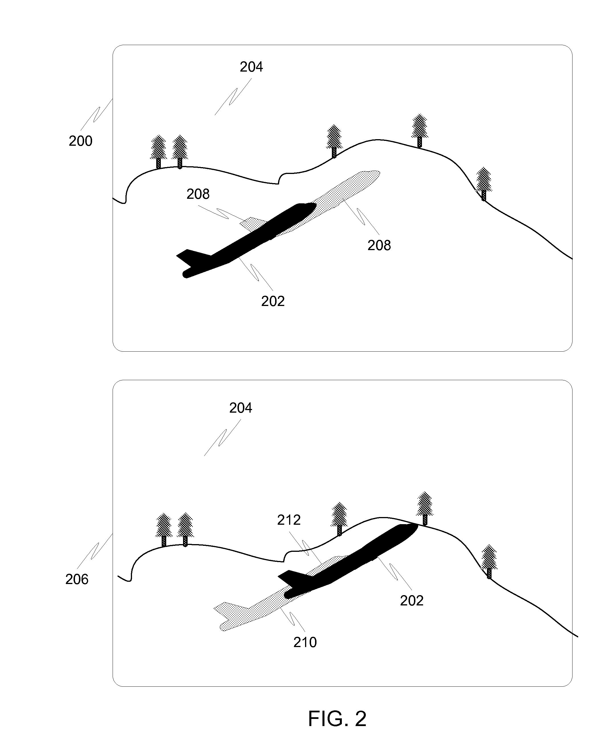
[0051]FIG. 2 is a diagram illustrating an example of conceal and reveal areas. In PREV frame 200, object 202 is in a certain location with respect to background 204. In CURR frame 206, the object 202 has moved to a different location with respect to background 204. The area 208 that the object has jus...

second embodiment

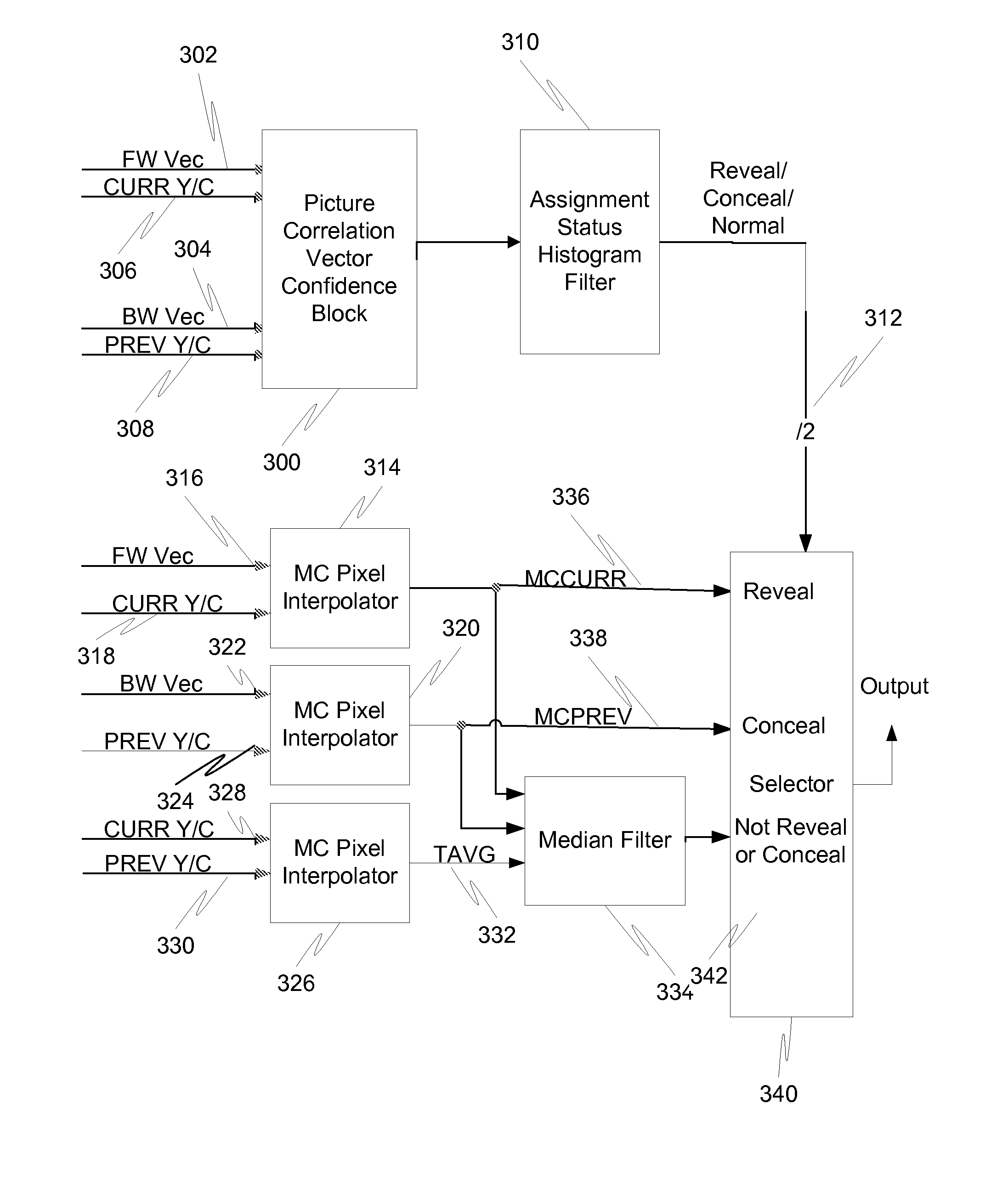
[0100]FIG. 9 is a block diagram illustrating an interpolation system in accordance with the present invention. A filtering and weighting unit 900 performs filtering and weighting on a field of input vectors. Those filtered and weighted vectors are then fed to a two dimensional histogram generator 902 that generates a two dimensional histogram of the vectors. An analysis unit 904 then analyzes the histogram for dominant vectors and estimates the background motion and the motion of any objects. Through this, a fade control signal can be generated based on the relative speed of an object. This fade control signal is fed to a blender 906, which blends output from a halo reducing interpolator 908 and a median interpolator 910 based upon the relative speed of an object.

[0101]FIG. 10 is a flow diagram illustrating a method for performing motion compensated interpolation using a previous frame and current frame of the displayable output in accordance with the second embodiment of the presen...

third embodiment

[0115]In the present invention, a camera model detects the predominant pan, rotation, and zoom parameters in a moving sequence. This information is then used to calculate a field of vectors that approximates the average motion over the whole frame. The approximate reveal or conceal areas on each edge of the frame to be interpolated are then calculated. The interpolator can use this to pull a pixel from the appropriate input frame when assembling this region. This camera model may be used in portions of the displayable area near the borders described above (the areas determined to be reveal or conceal areas), and aid in reducing or even eliminating the haloing issues caused by errors in other motion compensation algorithms.

[0116]The camera model may not, however, work very well if the movement is not caused by a pan, rotation, or zoom in a moving sequence (i.e., what appears to be a camera movement across a scene), but rather is caused by an object moving near one of the borders (e.g...


PUM


Abstract

In one embodiment of the present invention, motion compensated interpolation is performed by locating full frame conceal and reveal areas, determining intermediate frame occlusion areas of an interpolated frame of the displayable output by locating intermediate frame conceal areas based on projected locations of pixels within the full frame conceal areas using primary forward motion vectors and information about a time slot for the interpolated frame, and by locating intermediate frame reveal areas based on projected locations of pixels within the full frame reveal areas using primary backward motion vectors and information about the time slot for the interpolated frame. The intermediate frame conceal areas are then modified by projecting locations of pixels using secondary forward motion vectors and the intermediate frame reveal areas are modified by projecting locations of pixels using secondary backward motion vectors.

Description

CROSS REFERENCE TO RELATED APPLICATIONS[0001]This patent application is related and incorporates by reference in their entirety the following concurrently filed patent applications:(i) U.S. patent application Ser. No. ______ (Attorney Docket GENSP233 / 09-SCL-112) entitled “OCCLUSION ADAPTIVE MOTION COMPENSATED INTERPOLATOR” by Petrides;(ii) U.S. patent application Ser. No. ______ (Attorney Docket GENSP235 / 09-SCL-119) entitled “OBJECT SPEED WEIGHTED MOTION COMPENSATED INTERPOLATION” by Petrides;(iii) U.S. patent application Ser. No. ______ (Attorney Docket GENSP236 / 09-SCL-114) entitled “BORDER HANDLING FOR MOTION COMPENSATED TEMPORAL INTERPOLATOR USING CAMERA MODEL” by Petrides; and(iv) U.S. patent application Ser. No. ______ (Attorney Docket GENSP238 / 09-SCL-126) entitled “INTERMEDIATE FRAME OCCLUSION ESTIMATION SYSTEM USING PROJECTED VECTORS” by Petrides.FIELD OF THE INVENTION[0002]The invention relates to the display of images in a digital display, such as a television or monitor. M...

Claims


Application Information

Patent Timeline
IPC IPC(8): H04N5/00
CPCH04N19/105H04N19/139H04N19/51H04N19/553H04N19/17H04N19/82H04N19/513
Inventor PETRIDES, GORDON
Owner STMICROELECTRONICS SRL
Why Eureka
Try Eureka