Image encoding method and apparatus

Inactive Publication Date: 2005-08-30
CANON KK
View PDF8 Cites 159 Cited by
  • Summary
  • Abstract
  • Description
  • Claims
  • Application Information

AI Technical Summary

Benefits of technology

[0009]An object of the present invention is to provide an image encoding method and apparatus through whi

Problems solved by technology

The operation demanded of the user is therefore a complicated one.
Further, if it is so arranged that the image region to thus be encoded to a high image quality is determined by automatically discriminating the patterns or colors of this image, a limitation is imposed on the color

Method used


Image

  • Image encoding method and apparatus
  • Image encoding method and apparatus
  • Image encoding method and apparatus

Examples


first embodiment

[0030][First Embodiment]

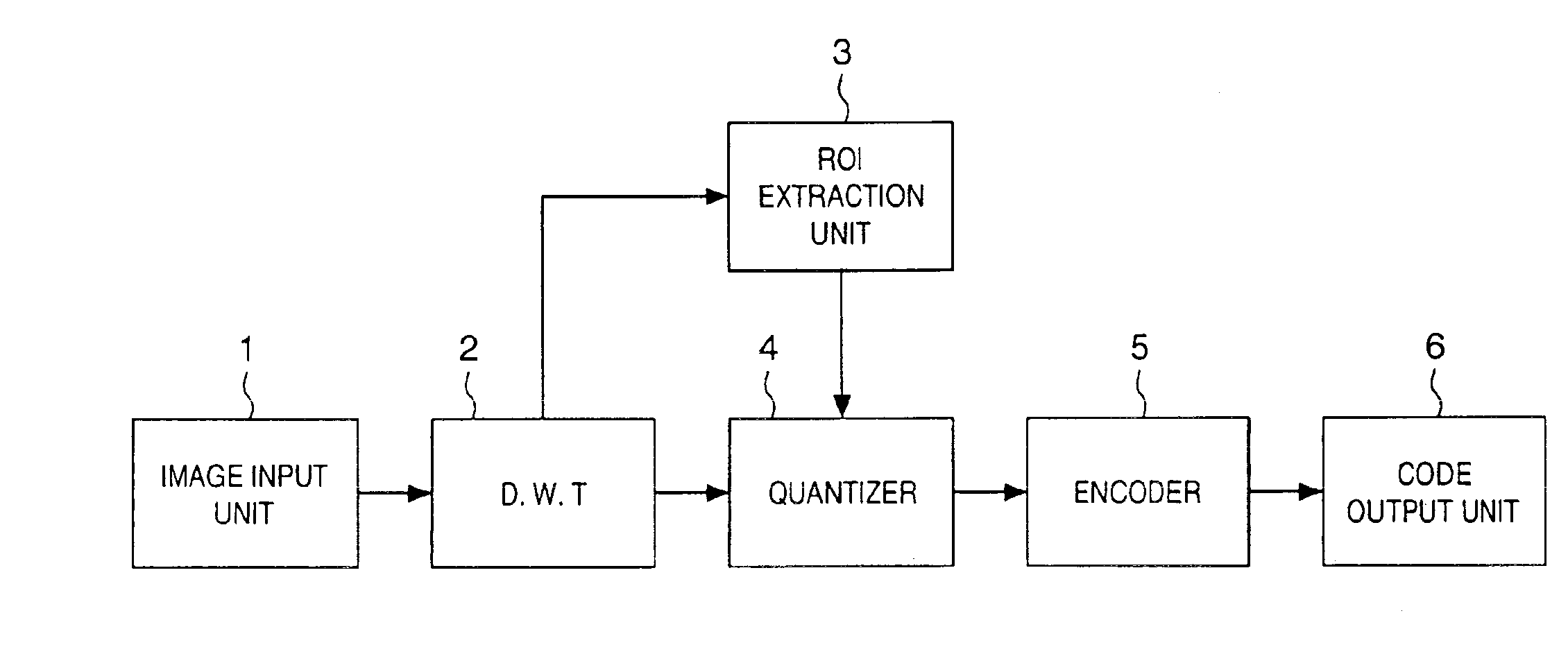
[0031]FIG. 1 is a block diagram illustrating the construction of an image encoding apparatus according to a first embodiment of the present invention.

[0032]As shown in FIG. 1, the apparatus includes an image input unit 1 for inputting image data. By way of example, the image input unit 1 is equipped with a scanner for reading a document image, with an imaging device such as a digital camera, or with an interface for interfacing a communication line. The input image is applied to a discrete wavelet transformation unit 2, which applies a two-dimensional discrete wavelet transform to the input image. An ROI (Region of Interest) extraction unit 3 extracts an ROI from the image that has entered from the image input unit 1. A quantizer 4 quantizes coefficients obtained by the two-dimensional discrete wavelet transform. An encoder 5 encodes the image signal that has been quantized by the quantizer 4, and a code output unit 6 outputs the code obtained by the encoder ...

second embodiment

[0066][Second Embodiment]

[0067]In the first embodiment described above, motion vectors within an image are detected minutely using subband signals obtained by application of the Haar wavelet transform, and an ROI is extracted based upon the distribution of these motion vectors. In the second embodiment, an ROI having left-right symmetry is extracted within an image having substantial left-right symmetry, such as an image of the human face, using subband signals obtained by application of the Haar wavelet transform in a manner similar to that of the first embodiment.

[0068]FIG. 7 is a block diagram illustrating the construction of the ROI extraction unit 3 according to the second embodiment for extracting an ROI having left-right symmetry. The ROI extraction unit 3 includes an arithmetic unit 40 for calculating degree of left-right symmetry and a region segmentation unit 41.

[0069]As shown in FIG. 7, in subbands obtained from the preceding two-dimensional discrete wavelet transformatio...

third embodiment

[0086][Third Embodiment]

[0087]In the first embodiment described above, motion vectors within an image are detected minutely utilizing subband signals obtained by application of the Haar wavelet transform, and an ROI is extracted based upon the distribution of these motion vectors. In the second embodiment, an ROI having left-right symmetry is extracted in similar fashion using subband signals obtained by application of the Haar wavelet transform. Next, in the third embodiment, segmentation of an input image into regions is carried out utilizing subband signals obtained by application of a wavelet transform and a region of interest in the input image is extracted.

[0088]An image having a low resolution often is used to perform region segmentation efficiently. The reason for this is that a region within an image contains more global image information, unlike edge information, for example. Accordingly, first the input image is subjected to region segmentation coarsely using the subband ...


PUM


Abstract

An image signal is input from an image input unit and is divided into different spatial frequency bands by applying a discrete wavelet transform thereto using a discrete wavelet transformation unit. On the basis of values of spatial frequency components, a region-of-interest extracts a region of interest by obtaining a distribution of motion vectors in the input image. A quantization unit applies quantization processing to the extracted region of interest and different quantization processing to other regions, and an encoder encodes the quantized image signal. Alternatively, motion of an image contained in the input image may be detected and the region of interest may be obtained based upon motion of this image.

Description

FIELD OF THE INVENTION[0001]This invention relates to an image encoding method and apparatus for encoding an input image by applying quantization processing that differs for each region of the image.BACKGROUND OF THE INVENTION[0002]Recent advances in digital signal processing technology have made it possible to efficiently encode large quantities of digital information such as moving and still pictures and video and to record the encoded information on a small-size magnetic medium or to transmit it to a communication medium.[0003]A technique using the discrete wavelet transform is known as a highly efficient method of encoding an image. In accordance with this technique, the discrete wavelet transform is applied to an input image signal to be encoded. In the discrete wavelet transform, two-dimensional discrete wavelet transform processing is applied to an input image signal, and then a sequence of coefficients obtained by the discrete wavelet transform is quantized.[0004]In such qua...

Claims


Application Information

Patent Timeline
IPC IPC(8): G06K9/00G06K9/36H04N7/12H04N7/26
CPCH04N19/139H04N19/63H04N19/61H04N19/124H04N19/17
Inventor NOZAWA, SHINGOKONDO, TOSHIAKI
Owner CANON KK
Why Eureka
Try Eureka