Transcoding

a video signal and transcoding technology, applied in the field of transcoding video signals, can solve the problems of high bandwidth and expensive transmission, and achieve the effect of reducing the cost of transmission

Inactive Publication Date: 2003-09-23
BRITISH TELECOMM PLC
View PDF17 Cites 165 Cited by
  • Summary
  • Abstract
  • Description
  • Claims
  • Application Information

AI Technical Summary

Problems solved by technology

Broadcast quality television requires in excess of 100 Mbit/s when transmitted ...

Method used


Image

  • Transcoding
  • Transcoding
  • Transcoding

Examples


Embodiment Construction

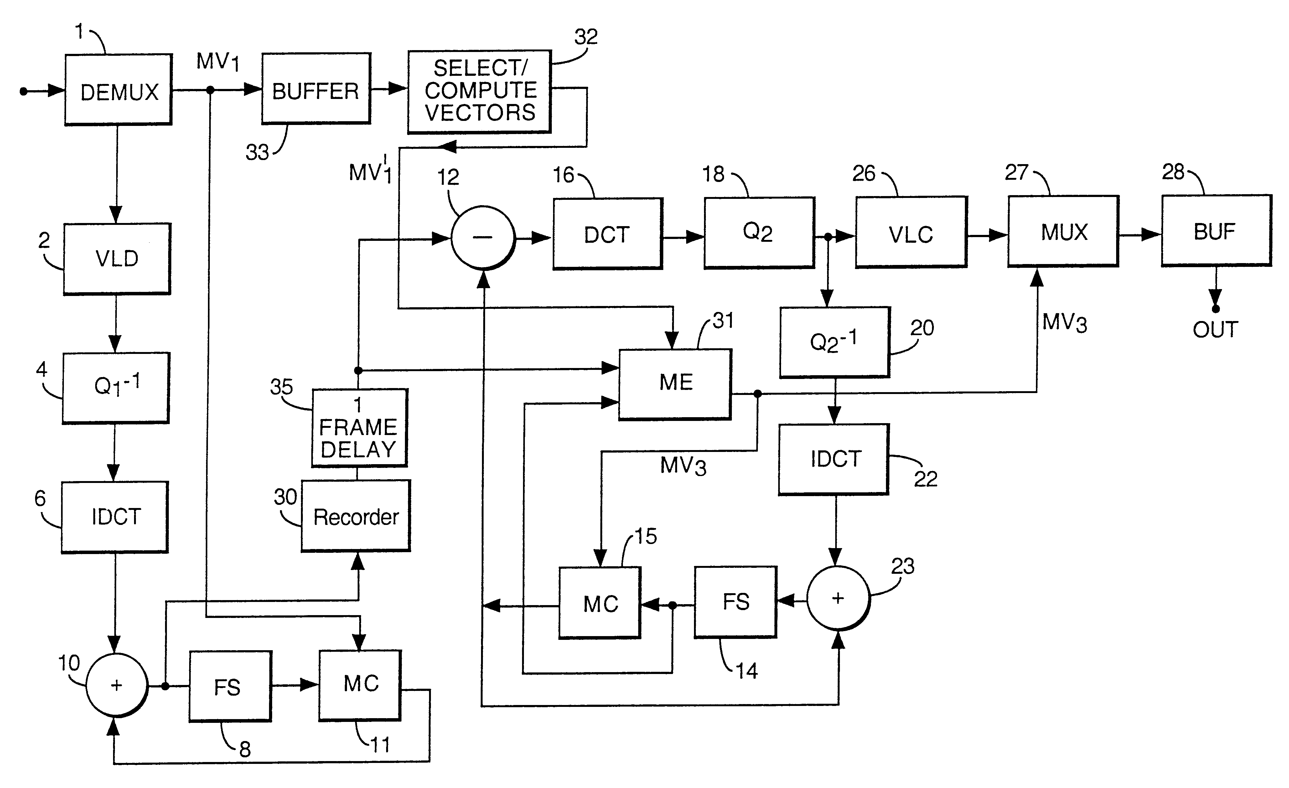
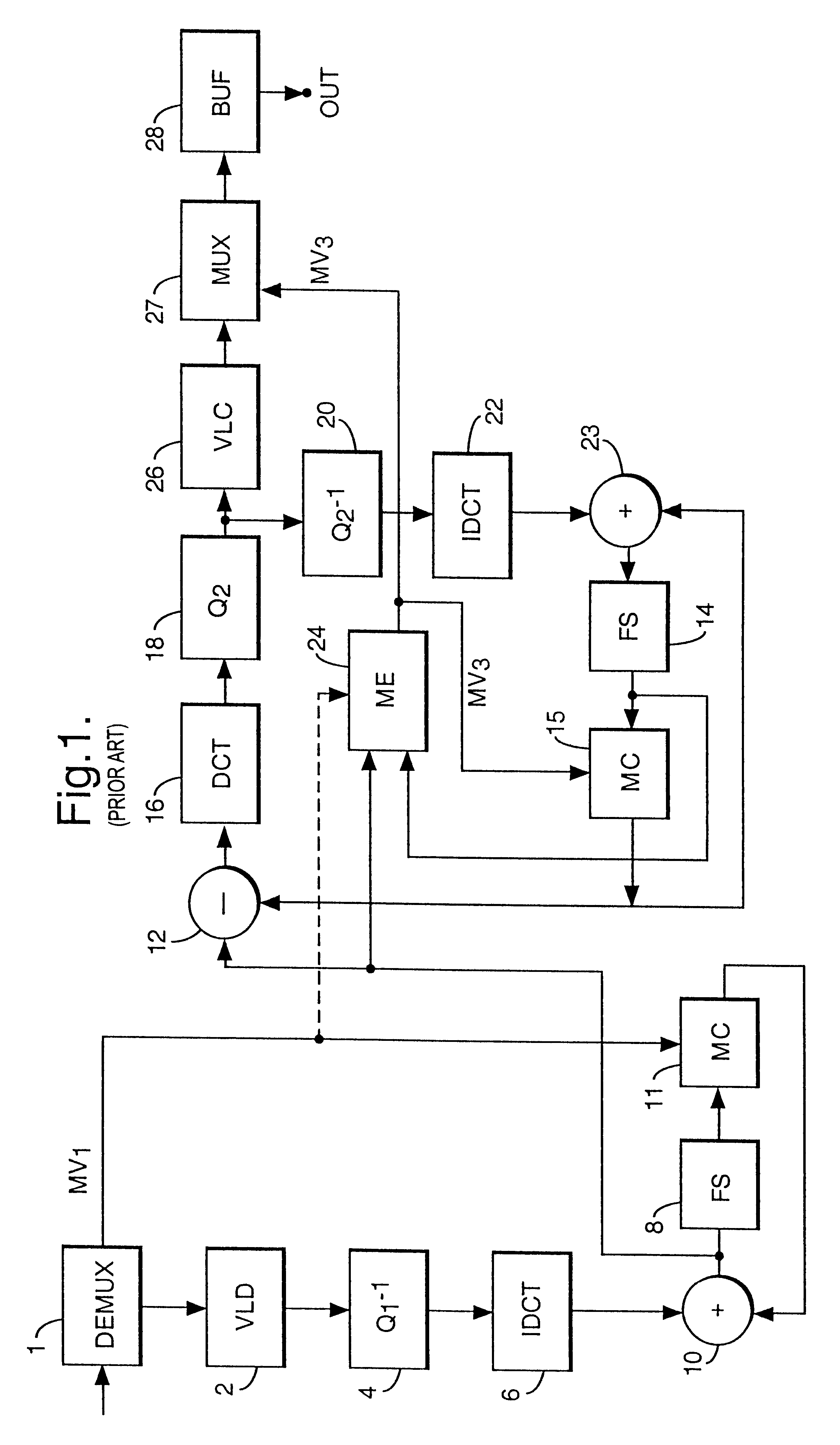
A transcoder is used to convert signals encoded according to a first format into signals encoded according to a second format. FIG. 1 shows a known form of transcoder which is arranged to convert video signals coded at a particular bit rate (e.g. 64 k bit / s) conforming to the H.261 standard to video signals coded at a lower rate (e.g. 32 k bit / s) conforming to the H.261 standard. Clearly the transcoder may, in practice, be arranged to convert signals from and to other formats.

The decoder part of the transcoder shown in FIG. 1 comprises a de-multiplexer 1 which receives an incoming coded data stream conforming to the H.261 standard and de-multiplexes the data stream into its constituent parts of compressed video data and motion vectors. The compressed video data is then decoded by a variable length decoder (VLD) 2, and then passes to an inverse quantiser 4 which outputs values of the discrete cosine transform (DCT) coefficients. The DCT coefficients are then transformed back into the...


PUM


Abstract

Transcoding is achieved by decoding a received video signal which has been coded according to a first coding scheme employing motion compensation and carries coded data and motion compensation information, and encoding the decoded according to a second coding scheme also employing motion compensation. Estimated motion vectors are generated for a current frame of the video signal, using vectors which, in the received signal, accompanying at least one other frame of the video signal. These may be used directly or used to define a search area for motion estimation.

Description

1. Field of the InventionThis invention relates to a method and apparatus for transcoding video signals from a first format into a second format.2. Related ArtMany techniques for compression of video signals are known. Broadcast quality television requires in excess of 100 Mbit / s when transmitted in digital form, which is expensive to transmit and requires links of high bandwidth. Known compression coding techniques may be used which take advantage of the high degree of spatial and / or temporal redundancy in the video signals being encoded. So, for example, in videoconferencing applications, compression down to a bit rate of a few hundred kilobits per second is possible whereas videotelephone quality pictures including sound can be compressed down to only 64 kilobits per second, equivalent to a single telephone channel.One known compression technique is predictive coding which exploits the assumption that a picture element (pixel) within a frame is related to neighbouring pixels in t...

Claims


Application Information

Patent Timeline
IPC IPC(8): H04N7/36H04N7/26H04N7/32
CPCH04N19/51H04N19/40
Inventor NILSSON, MICHAEL EGHANBARI, MOHAMMED
Owner BRITISH TELECOMM PLC
Why Eureka
Try Eureka