Vertical windmill

Inactive Publication Date: 2011-09-01
NGUYEN HUY T
View PDF10 Cites 20 Cited by
  • Summary
  • Abstract
  • Description
  • Claims
  • Application Information

AI Technical Summary

Benefits of technology

[0008]The vertical windmill includes a rotatable wind wheel column mounted to a base. The column includes a plurality of hollow wheel hubs stacked vertically atop each other. Each wheel hub includes a plurality of radiating mounting arms equidistantly spaced around the axis of the wheel hub so that the arms of an adjacent hub are angularly offset with respect to the other. A plurality of mounting assemblies is disposed on each of the mounting arms for mounting an array of wing blades. Each alternate stacked wheel hub and corr

Problems solved by technology

The supply of fossil fuels dwindles annually, and they produce tons of hazardous chemicals dangerous to dispose of without strict regulation.
Moreover, it is difficult to find safe landfill real estate that does not encroach on livable land.
However, this particular configuration still does not maximize conversion of wind power to rotary force due to the weight of the blades despite the

Method used


Image

  • Vertical windmill
  • Vertical windmill
  • Vertical windmill

Examples


Embodiment Construction

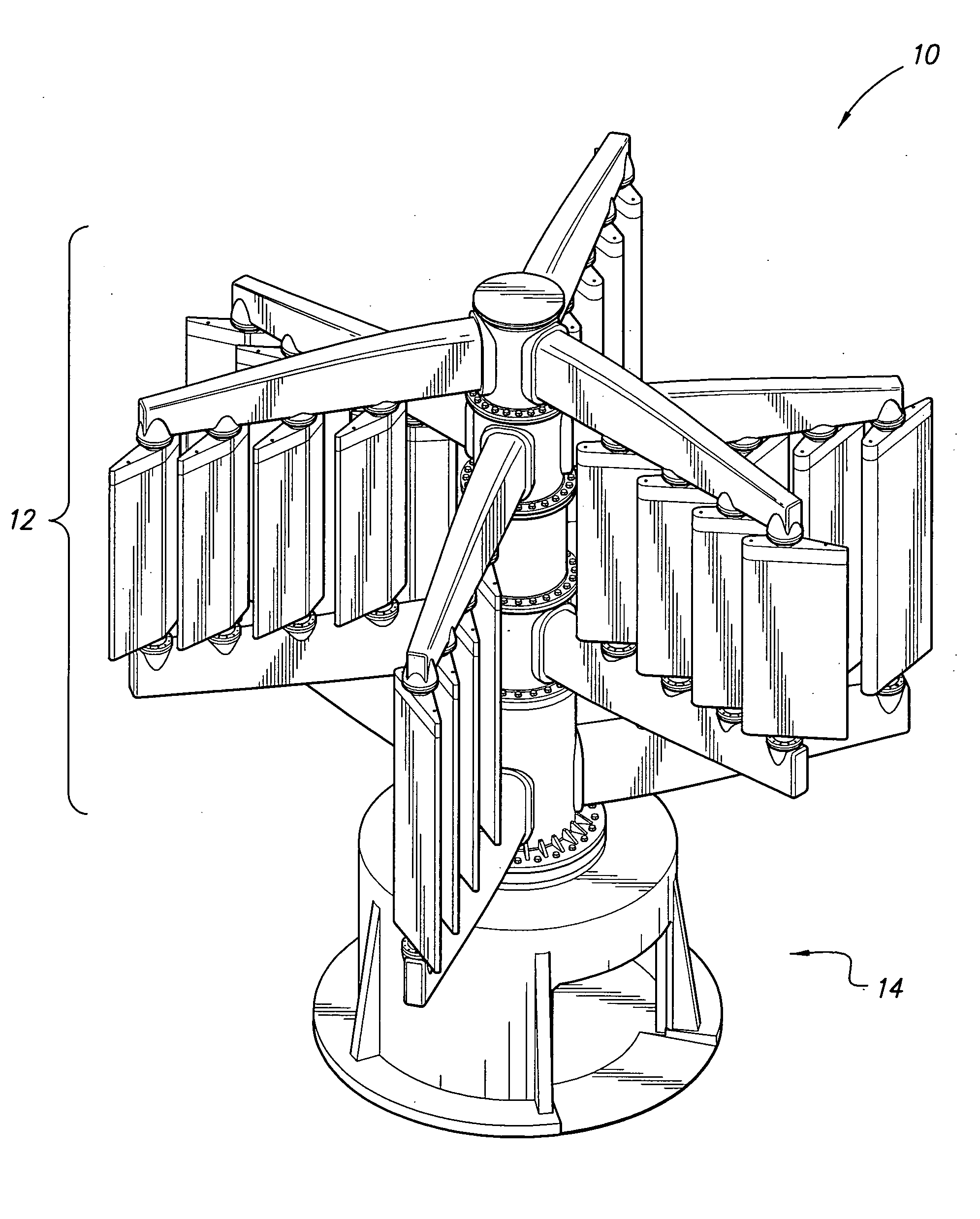
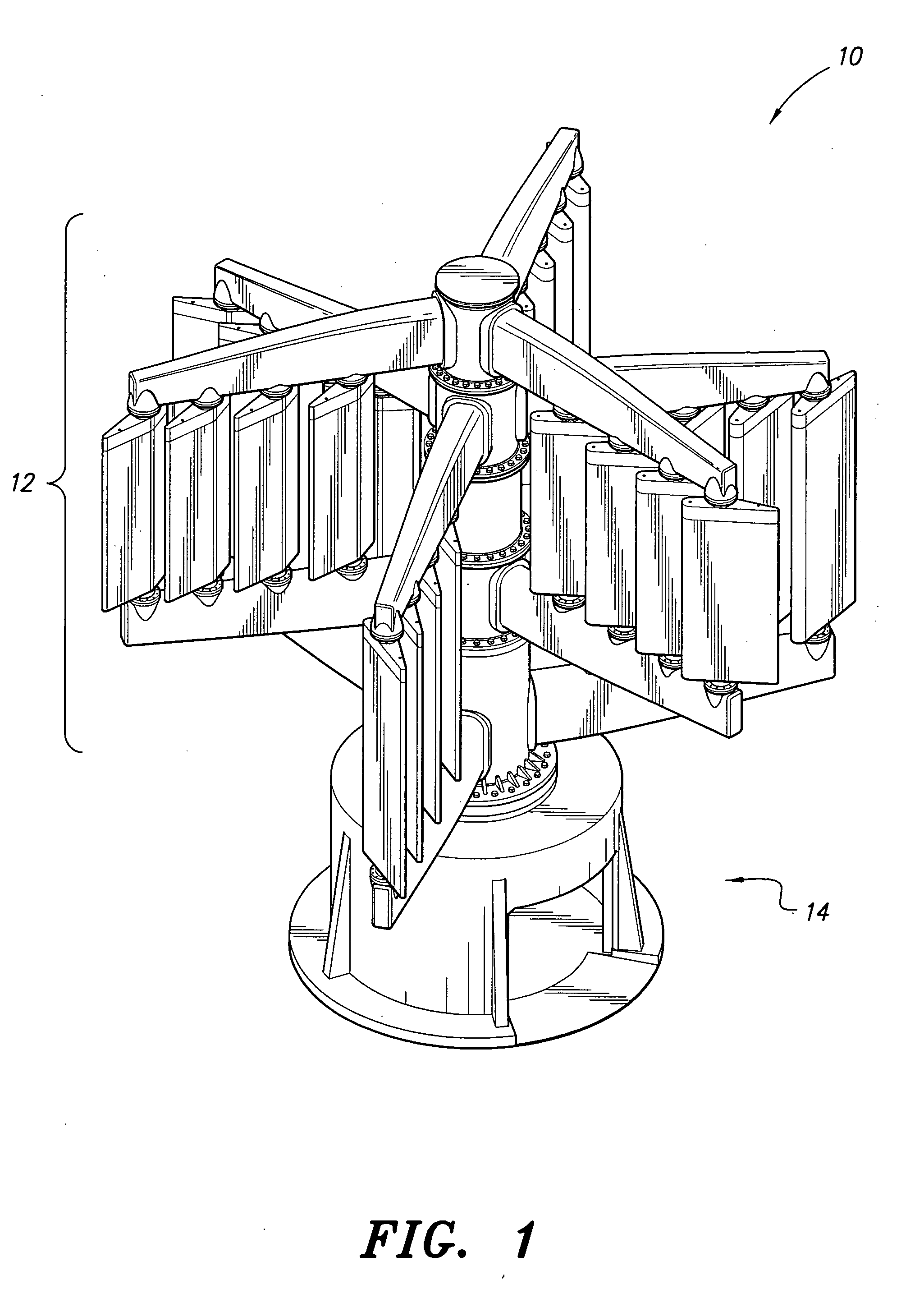
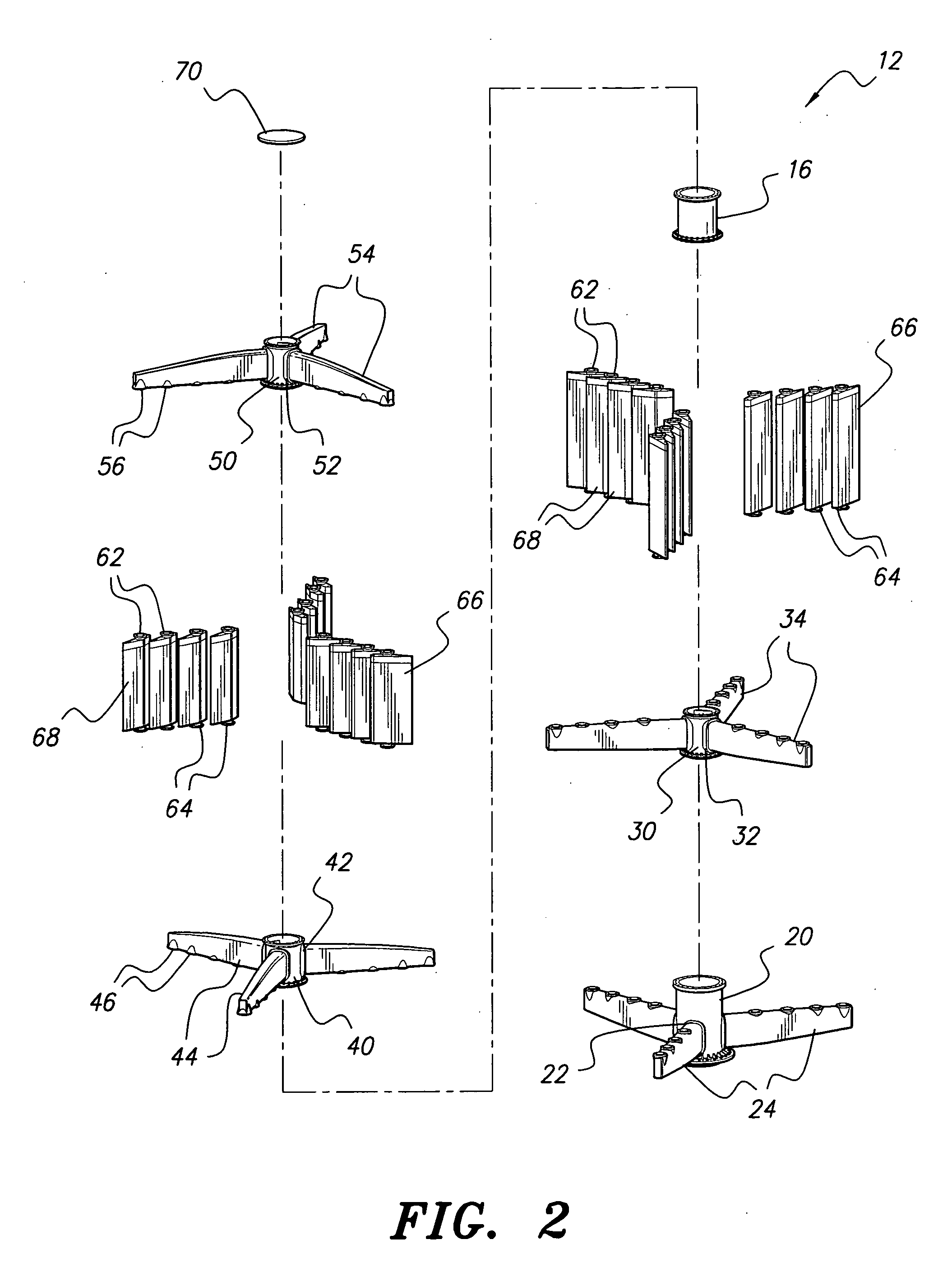
[0018]The present invention relates to a vertical windmill, generally referred to in the drawings by reference number 10, for maximal conversion of wind power into rotary force for producing usable energy. As shown in FIGS. 1 and 2, the vertical windmill 10 includes a rotatable wind wheel column 12 mounted to a base 14. The wind wheel column 12 includes a plurality of vertically stacked wind wheels angularly offset or staggered from each other. A plurality of vertically disposed vanes, wings or blades 60 mounted to the wind wheels utilizes wind power to provide the motive force for rotating the wind wheel column 12.

[0019]As shown in FIG. 2, the wind wheel column 12 includes, from the bottom, a lower or first hub 20 with angularly spaced mounting holes 24. The first hub 20 may be a substantially hollow cylinder with connection flanges disposed on the top and bottom to facilitate mounting thereof to subsequent hubs or hub sections and the base 14. Since the first hub 20 forms a base o...


PUM


Abstract

The vertical windmill includes a rotatable wind wheel column mounted to a base. The column includes a plurality of hollow wheel hubs stacked vertically atop each other. Each wheel hub includes a plurality of radiating mounting arms equidistantly spaced around the axis of the wheel hub such that the arms of an adjacent hub are angularly offset with respect to the other. A plurality of mounting assemblies is disposed on each of the mounting arms for mounting an array of wing blades. Each alternate stacked wheel hub and mounting arms together forms a wind wheel with vertically oriented wing blades mounted between upper and lower spaced arms such that the top wheel is interconnected with the lower wheel at a height less than the height of the blades. Each array of blades may freely rotate or be positively rotated to orient the blades for optimum usage of wind power in rotating the column.

Description

BACKGROUND OF THE INVENTION[0001]1. Field of the Invention[0002]The present invention relates to alternative energy generating devices, and more specifically to a vertical windmill for maximizing conversion of wind energy into usable energy.[0003]2. Description of the Related Art[0004]Due to the ever-increasing energy demands and the negative environmental impact of fossil and nuclear fuels, pursuit of green alternatives have become a prominent concern worldwide. The supply of fossil fuels dwindles annually, and they produce tons of hazardous chemicals dangerous to dispose of without strict regulation. Nuclear reactors produce radioactive wastes that take decades before the radioactivity diminishes to safe levels. Moreover, it is difficult to find safe landfill real estate that does not encroach on livable land.[0005]With the above concerns in mind, many different alternative methods for generating usable energy have been pursued utilizing the power of the elements such as solar, wa...

Claims


Application Information

Patent Timeline
IPC IPC(8): F03D7/06
CPCF03D3/067F03D3/068Y02E10/74Y02E10/721F05B2260/72Y10S415/907Y02E10/72
Inventor NGUYEN, HUY T.
Owner NGUYEN HUY T
Why Eureka
Try Eureka