Wind power generation system

a power generation system and wind turbine technology, applied in wind motors, reaction engines, motors, etc., can solve the problems of high tip speed, high material strength limit, lateral flow and flow separation from the low pressure side of the blade, etc., to reduce the rotational moment of inertia, reduce the stall characteristics of the blade, and reduce the effect of lifting coefficien

Active Publication Date: 2011-09-01
GARDEN ENERGY
View PDF12 Cites 20 Cited by
  • Summary
  • Abstract
  • Description
  • Claims
  • Application Information

AI Technical Summary

Benefits of technology

[0012]Advantageously, the aerodynamic section dividers, when appropriately placed, soften the stall characteristics of the blade. As a result, high lift coefficient airfoils may be used at high angles of attack. The short blades provide structural stability and lower rotational moments of inertia. As a result, blades provide increased torque and efficiency, and more tolerance to atmospheric turbulence over a wider productive operating range in varying types of atmospheric conditions.

Problems solved by technology

Commercial wind turbines typically have long, thin blades (e.g., 150+ ft.) which lead to very high tip speeds, and thus have to address significant differential loading and performance concerns over the length of the blades.
As a consequence of their length, blades often approach the limits of material strength, and are sensitive to the magnitude of rotational and aerodynamic loading.
Minor boundary layer disruptions (e.g., turbulence) interacting with a wind turbine blade appear as variations in effective angle of attack, and can lead to lateral flow and flow separation from the low pressure side of the blade.
Such separation (e.g., stall) negatively impacts performance, and potentially can lead to failure of the blades (which are typically large flexible structures).
Such airfoils are less aerodynamically efficient, having lift to drag ratios in the range of 40 to 60.

Method used


Image

  • Wind power generation system
  • Wind power generation system
  • Wind power generation system

Examples


Embodiment Construction

[0023]The invention summarized above and defined by the enumerated claims may be better understood by referring to the following detailed description, which should be read with the accompanying drawings. This detailed description of particular preferred embodiments of the invention, set out below to enable one to build and use particular implementations of the invention, is not intended to limit the enumerated claims, but rather, it is intended to provide particular examples of them. Furthermore, there is no intent to be bound by any expressed or implied theory presented in this application.

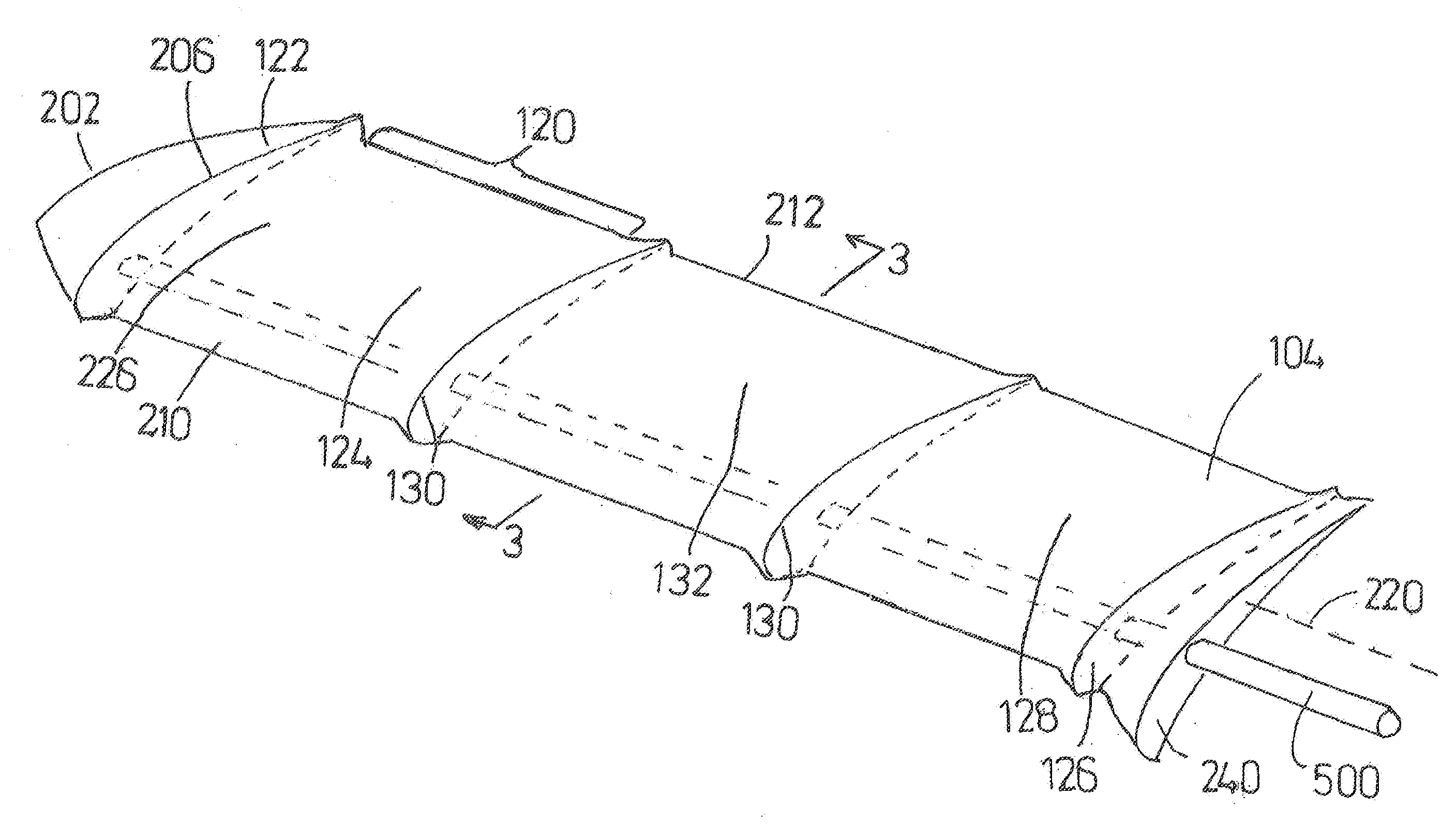
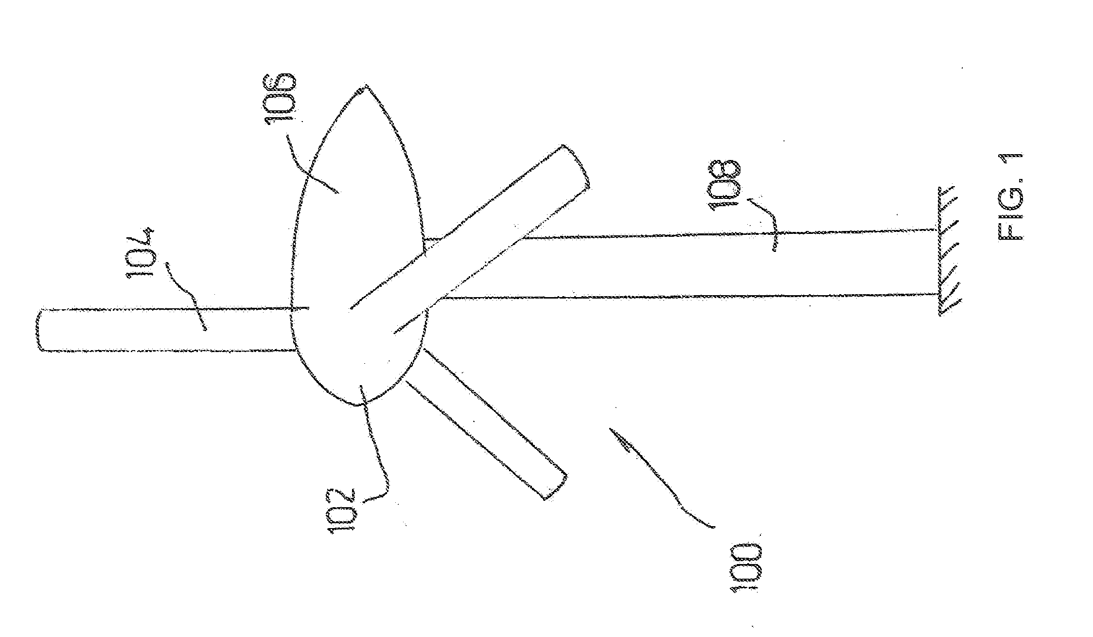
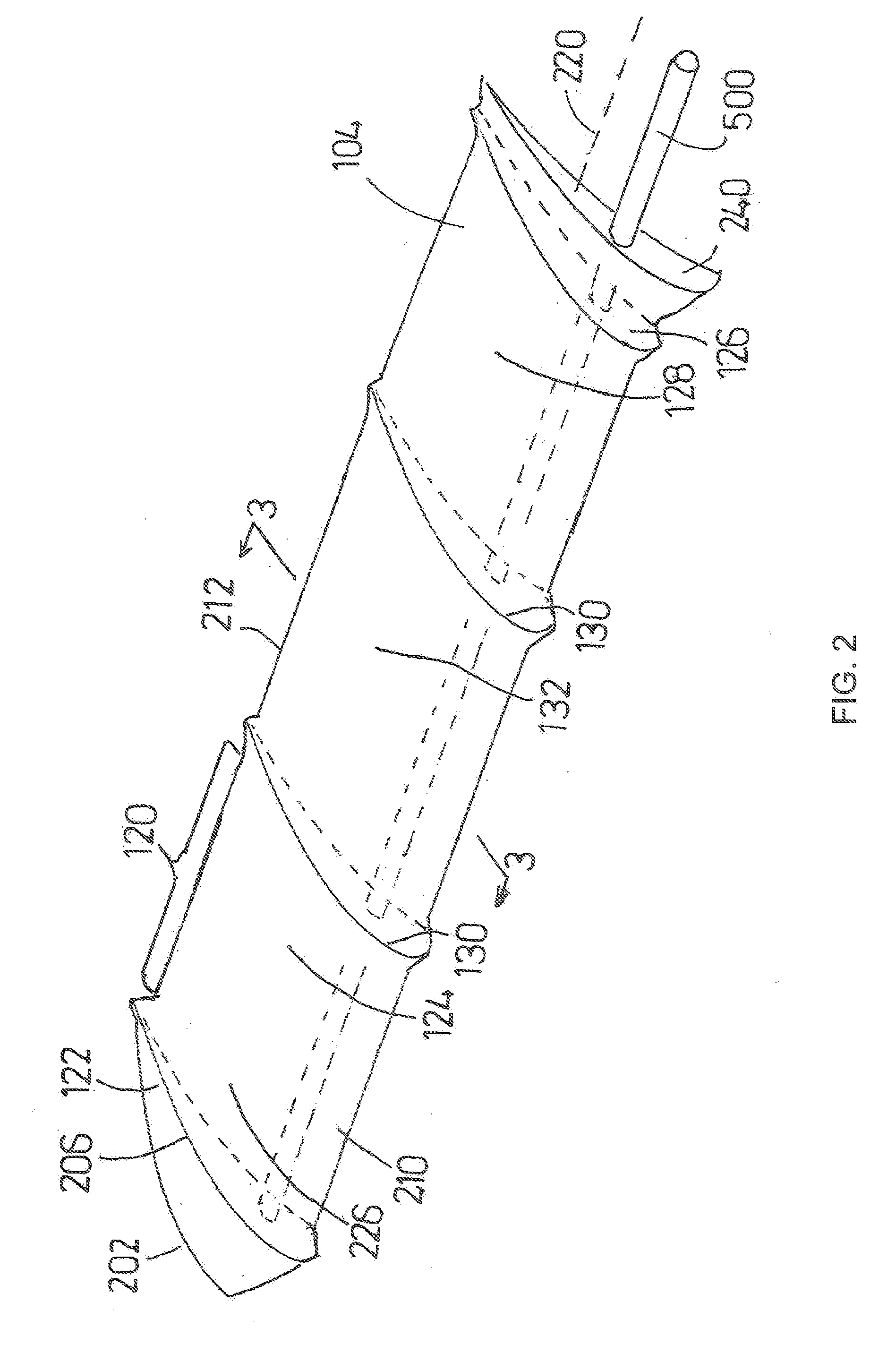
[0024]Typical embodiments of the present invention reside in a wind-power electrical generation system providing a greater ability to capture kinetic energy from wind. With reference to FIGS. 1 to 3, a first embodiment of a wind-power electrical generation system 100 includes a hub 102 or nose cone which houses various electrical and mechanical turbine components. A blade group, including one or ...


PUM


Abstract

A wind turbine blade forming a root at an inner end, a tip at an outer end, a plurality of power sections intermediate the root and the tip, and a plurality of aerodynamic section dividers located intermediate each of the other sections. The aerodynamic section dividers are configured to aerodynamically isolate their adjoining sections to limit the lateral flow of air between them while in use on the wind turbine. The blade has a low aspect ratio and is operated at a high advance rate. The aerodynamic section dividers are close enough together to soften the stall characteristics of the blade, and thus the blade can be operated at high angles of attack.

Description

[0001]This application claims the benefit of U.S. provisional Application No. 61 / 337,356, filed Feb. 2, 2010, which is incorporated herein by reference for all purposes.[0002]The present invention relates to a wind-power electrical generation system having aerodynamic elements providing a greater ability to capture kinetic energy by improving lift, reducing drag, and / or expanding the operating envelope of the generator.BACKGROUND OF THE INVENTION[0003]The use of windmill blades has been known for facilitating varied activities such as pumping water, processing grain and supplying electricity. As early as the 1930s, horizontal axis wind turbines became popular and cost effective for the supply of electricity where the turbine drive train apparatus was mounted horizontal to the ground. It is desirable for wind generator blades have high lift, minimum drag, and a broad operating envelope.[0004]For a typical wind power generator, the kinetic energy extracted from the wind by wind turbin...

Claims


Application Information

Patent Timeline
Patent Type & Authority Applications(United States)
IPC IPC(8): F01D5/14
CPCF03D1/0633Y02E10/721F05B2250/70F05B2240/30Y02E10/72F03D1/0675
Inventor WATTS, PHILIPEATS, JAMES V.
Owner GARDEN ENERGY
Why Eureka
Try Eureka