Device for Displaying a Graphic Holder

a technology for graphic holders and devices, applied in the field of display of graphic holders, can solve the problems of preventing the placement and removal of goods on or from display arms, preventing the possibility of injuring users, and preventing so as to prevent excessive stretching or twisting of the neck portion, and the effect of lifting up is fairly easy

Active Publication Date: 2011-09-15
ASHBROOK REES LTD
View PDF2 Cites 1 Cited by
  • Summary
  • Abstract
  • Description
  • Claims
  • Application Information

AI Technical Summary

Benefits of technology

[0021]Preferably, the neck portion of a device according to the present invention substantially comprises a first side wall attached to a first side of the body portion at a first end, a second side wall attached to a second side of the body portion at a first end and an end portion attached to a second end of the first side wall and a second end of the second side wall thereby substantially forming the second end of the neck portion. Although the neck portion of the device of the present invention may alternatively be formed as a single solid portion or a single planar wall it is preferable that the neck portion is substantially formed of first side wall, a second side wall and an end wall, as set out above. This is because a neck portion formed in this manner is relatively lightweight but resilient. In particular, a neck portion formed of two substantially parallel side walls will be more resistant to twisting than a neck portion formed of a single wall. The presence of an end wall attached to the first and second side walls further reinforces the neck portion in a lightweight manner.
[0022]If the neck portion has a first side wall and a second side wall they may have reinforcing portions substantially at each of their edges. The reinforcing portions may be portions of increased thickness substantially extending along, or adjacent to, the edges of the side walls from their first end to their second end. Reinforcing portions are advantageous as they strengthen the side walls in a lightweight and simple manner. Suitably formed reinforcing portions can prevent excessive stretching or twisting of the neck portion.
[0023]Advantageously, if a neck portion of a device according to the present invention is formed of a first side wall, a second side wall and an end wall the first side wall and the second side wall may be substantially parallel and extend in a plane parallel to an axis of the band of the body portion and the end portion of the neck portion may be substantially perpendicular to the axis of the band of the body portion. For example, the first side wall and the second side wall may extend vertically upwards from the body portion of the device in a plane parallel to one another and parallel to the axis of the band of the body portion, the first and second side walls may bend through approximately ninety degrees such that their second ends, and the end wall, are substantially vertical and in a plane perpendicular to the axis of the body portion. This arrangement is advantageous as it means that the end wall is substantially vertical and may be positioned directly above an opening of the band of the body portion of the device. This enables a graphic holder to be attached to the end wall of the device and be supported in a substantially vertical position adjacent to an end of a display arm when the device is positioned on the display arm, adjacent to its end.
[0024]Furthermore, this method of locating the end wall is preferable as it means that is difficult to rotate a top edge of the end wall downwards, towards an opening of the band of the device. This is due to the difficulty in stretching the first and second side walls in this direction. In contrast, it is relatively easy to rotate the top edge of the end wall upwards, towards a top side of the band of the device, as the first and second side walls can be compressed in this direction. As will be readily appreciated, in practice, this allows a graphic holder attached to the end wall of the device to be lifted upwards fairly easily whilst preventing the downward rotation of the graphic holder, where it might impact an end of a display arm or the goods displayed thereon.
[0025]In order to facilitate the rotation of the device and an attached graphic holder, as set out in the paragraph immediately above, it is advantageous that an edge of the end portion extending between the first side wall and the second side wall is substantially adjacent to the band of the body portion and is separated from the body portion by a notch. The notch may either comprise a zone of reduced thickness or a gap formed between the edge of the end portion and the body portion. The presence of this notch makes the rotation of a top edge of the end wall back towards a top side of the band of the device easier as it means it is not necessary to stretch a relatively thick portion of material that might otherwise be present between an edge of the end portion and the body portion.

Problems solved by technology

Nevertheless, graphic holders formed in this manner do impede the placing and removal of goods on or from a display arm.
Furthermore, graphic holders formed in this manner are typically formed of hard plastics and are prone to breakages and may even injure customers.
The new device should also be resistant to breakages and should definitely not provide any possibility of injuring a user.

Method used


Image

  • Device for Displaying a Graphic Holder
  • Device for Displaying a Graphic Holder
  • Device for Displaying a Graphic Holder

Examples


first embodiment

[0056]The graphic holder 30 of FIG. 13 can be rotatably attached to the device 1 by pushing the second stop means 42 of the attaching means 37 through the aperture 13 formed in the end wall 10 of the device such that the axle of the attaching means 37 extends through the aperture 13 and the second stop means 42 is substantially located in the cutaway portion 14 formed in the inner wall of the end wall.

second embodiment

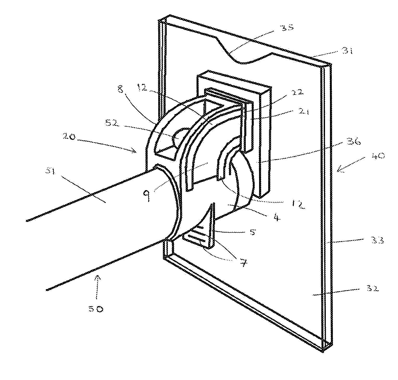
[0057]The graphic holder 40 of FIG. 14 has two horizontal slots 43 formed centrally in the attaching portion 36. These slots 43 allow the graphic holder 40 to be semi-permanently and non-rotatably mounted on the device 20. In particular, the graphic holder can be mounted on the device 20 by pulling the locating tab 21 through one of the slots 43 formed in the attaching portion. The parallel ridges 24 formed on the locating tab 21 assist the user in doing this. As will be readily appreciated, this must be done before the outer wall 31 of the graphic holder 40 is clipped to the inner wall 32. The horizontal slots 43 are formed such that they are a similar size and thickness to the joining portion 22 of the device 20 and the device 20 can thereby securely hold the graphic holder 40. As will be understood, the elastic nature of the material from which the device 20 is formed allows the locating tab 21 to be pulled through a horizontal slot 43 despite the fact that the locating tab 21 is...


PUM


Abstract

The present invention provides a device for mounting a graphic holder on a display arm. The device has a body portion substantially formed of a resilient elastic material. The body portion comprises a band for securing around a display arm. As the band is resilient and elastic it can be used to mount the device on a variety of different shaped display arms. The device further comprises a neck portion attached to the body portion at a first end and having attaching means for holding the graphics holder substantially at a second end. The present invention also provides a system for displaying a graphic on a display arm comprising a device and a graphic holder.

Description

FIELD OF INVENTION[0001]The present invention relates to the display of graphic holders on display arms in commercial premises, for example the display of price signs on clothing rails. In particular, the present invention provides an improved device for positioning a graphic holder on a display arm.BACKGROUND[0002]Many goods are displayed in shops on display arms. Typically, the goods will be hung below a display arm. This is beneficial allows a plurality of goods to be displayed on a shop floor in a relatively compact space. Most display arms comprise stop means positioned at the end of the display arm to prevent goods from sliding off the arm. Typically, display arms have a suitable stop means formed at or near the end of the display arm. Generally the stop means comprises a protrusion is formed on, and extends upwards from, an upper surface of the display arm. For example, some display arms have a small ball welded on an upper surface adjacent to the end of the display arm to ac...

Claims


Application Information

Patent Timeline
Patent Type & Authority Applications(United States)
IPC IPC(8): G09F3/00
CPCG09F3/201G09F7/20G09F3/204
Inventor ROWLAND, SIMONJOHNS, HELEN
Owner ASHBROOK REES LTD
Why Eureka
Try Eureka