Rotating Pipe Machining Device

a technology of rotating pipes and machining devices, which is applied in the direction of manufacturing tools, mechanical equipment, portable lathes, etc., can solve the problems of inability to position the bores that receive the mounting shafts of bearings to the degree of accuracy required, excessive force on one or more bearings, and wear and tear

Active Publication Date: 2011-09-15
ILLINOIS TOOL WORKS INC
View PDF6 Cites 31 Cited by
  • Summary
  • Abstract
  • Description
  • Claims
  • Application Information

AI Technical Summary

Problems solved by technology

If the bearings are not properly aligned, one or more of the bearings will be subjected to excessive forces and become worn.
As the bearings wear, the gearing between the rotating and stationary members will also become misaligned, with the alignment worsening as the bearings wear until failure occurs in either the bearings or the gearing.
However, the bores that receive the mounting shafts for the bearings cannot be positioned to the degree of accuracy required to maintain the proper balance of forces against the various bearings.
As acknowledged above, the operators of such devices have difficulty in balancing of the forces on the bearings.
Even after the forces have been balanced, it has been found that regardless how tightly the retaining nuts are tightened, the bearings of prior art machines tend to move out of balance over a relatively short period of time.
It has been found, however, that as the nut is tightened the shaft will tend to rotate through a small angle regardless of the technician's efforts to resist such movement.
Furthermore, split frame pipe machines typically have ten to sixteen of such bearings, and it is virtually impossible for a technician to equally balance the forces against all of the bearings.

Method used


Image

  • Rotating Pipe Machining Device
  • Rotating Pipe Machining Device
  • Rotating Pipe Machining Device

Examples


Embodiment Construction

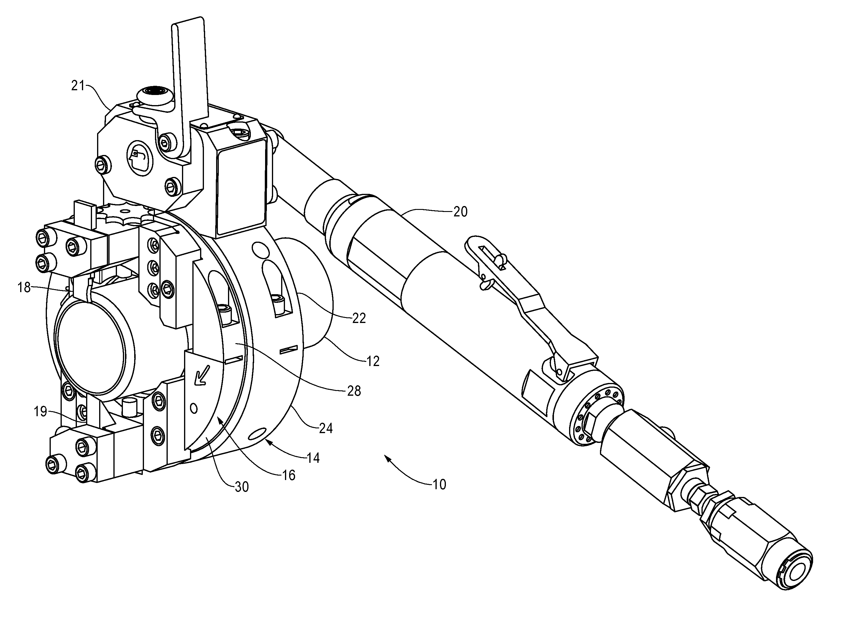
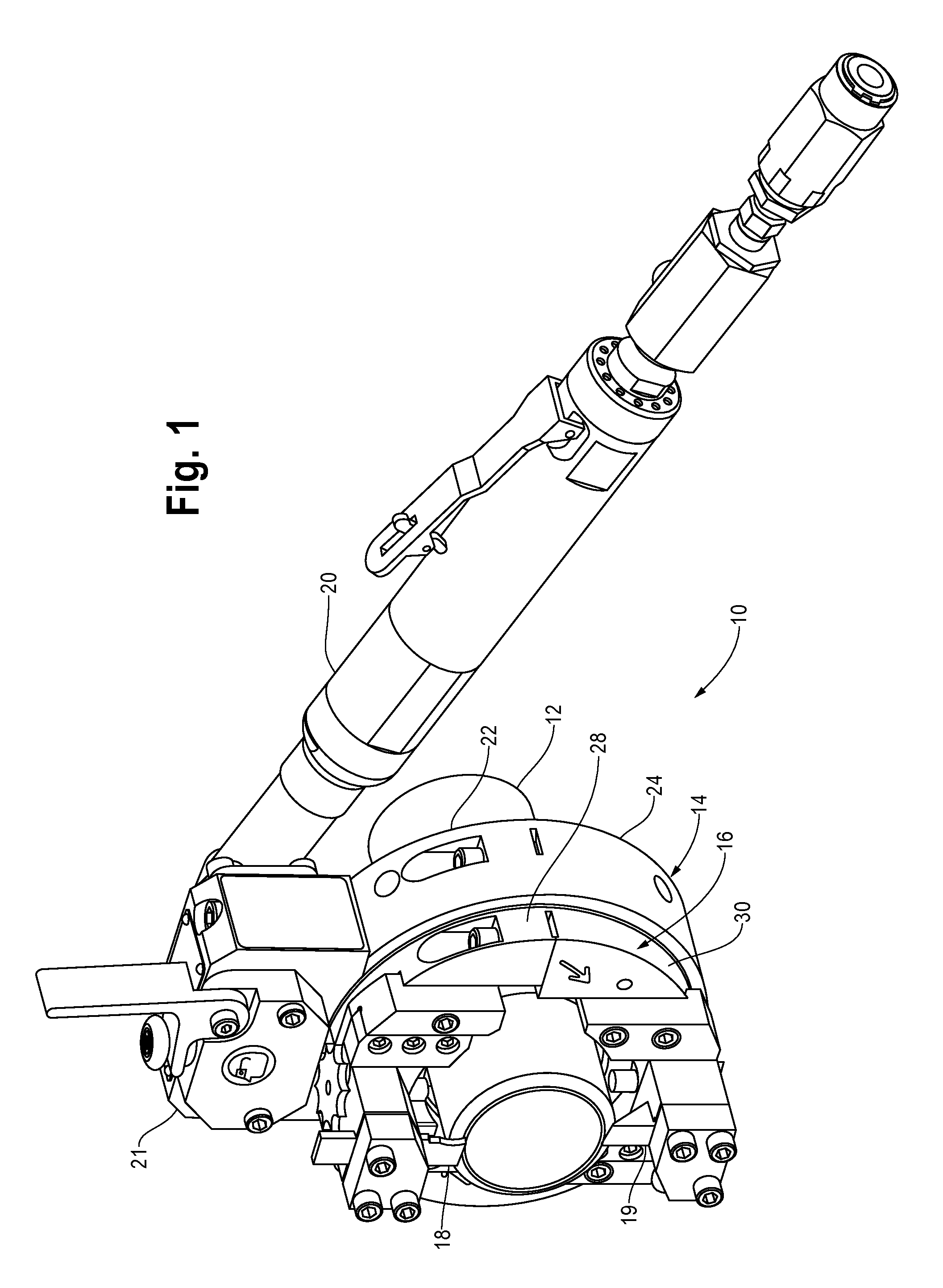
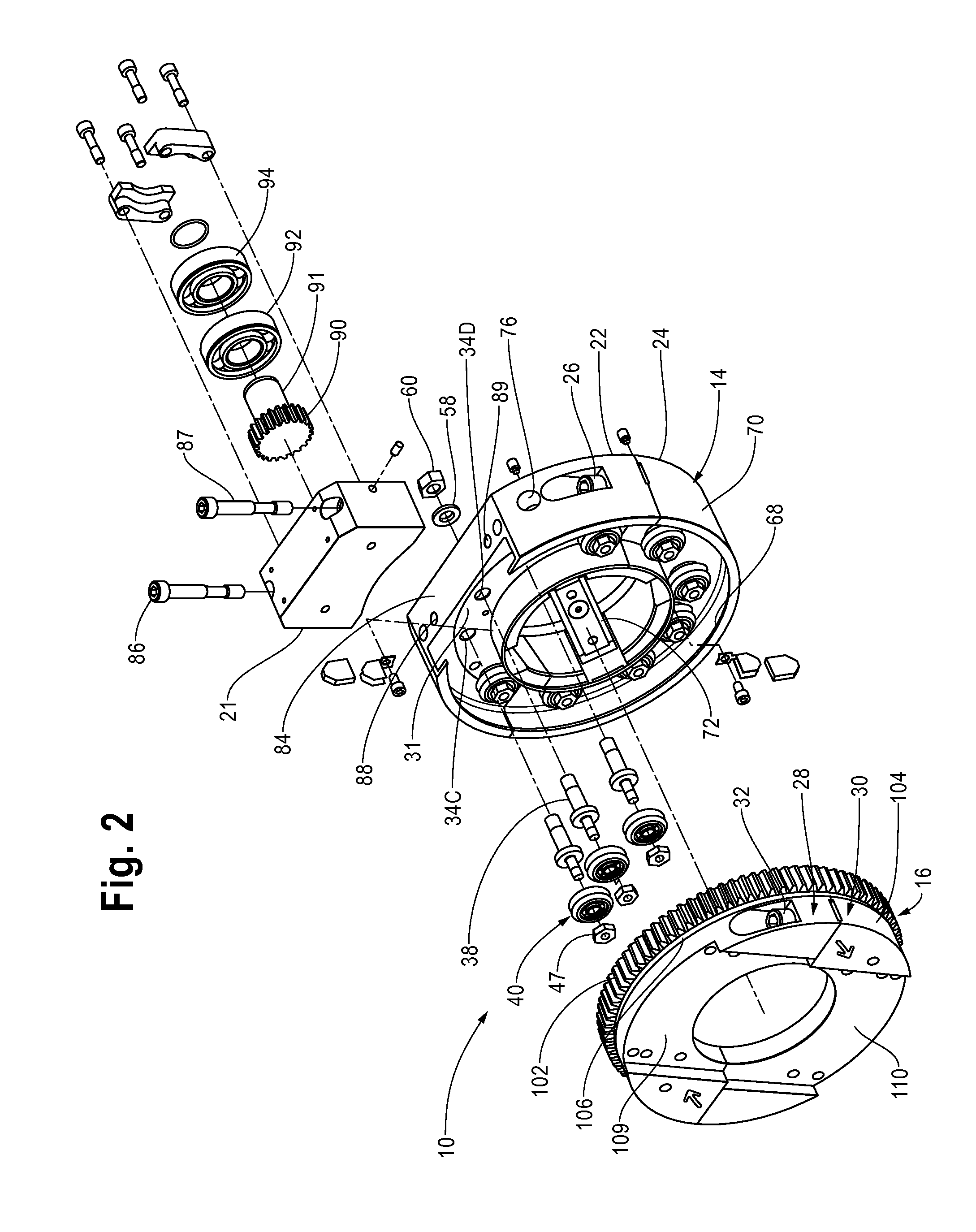
[0028]Referring to FIGS. 1, 2, and 3, a pipe machining device 10 for cutting or machining the end of a length of pipe 12 includes an annular stationary member 14 that is attachable to the outer surface of the pipe 12 and an annular rotatable member 16 that is rotatable with respect to the stationary member 14 for retaining a tool. Although FIGS. 1 and 2 depict the device 10 simultaneously retaining two tools 18, 19, it is common to use device 10 with one tool 18, 19 at a time. The annular rotatable member 16 is rotated with respect to the stationary annular member 14 by a motor 20 and a drive assembly within a pinion housing 21 on the annular stationary member 14. A tool mounting, unnumbered, urges the tool 18, 19 against a surface of the pipe 12 to thereby cut into the surface, or machine the surface a needed.

[0029]Referring to FIGS. 1, 2, 3, 3A, and 10, the annular stationary member 14 consists of a first arcuate portion 22 and a generally complementary second arcuate portion 24 t...


PUM

PropertyMeasurementUnit
circumferenceaaaaaaaaaa
lengthaaaaaaaaaa
diameteraaaaaaaaaa

Abstract

A machining device has a stationary member and a rotating member. A plurality of bearings on one of the members engages a surface of the other. At least one of the bearings is radially fixed, while the remainder of the bearings are radially adjustable. In another aspect of the invention, the bearings are rotatable on a first cylindrical portion of a mounting shaft that has a second cylindrical portion attachable to the machine. A radial undercut is provided around a flange between the first cylindrical portion and the second cylindrical portion.

Description

[0001]The present invention relates to machines that cut pipe, and prepare the ends of pipe for welding, and in particular to a split frame pipe machining device.BACKGROUND OF THE INVENTION[0002]The present invention relates to pipe preparation machines for cutting a length of pipe, and preparing the end of the pipe to receive a welding. Where the end of a length of pipe is accessible, a cutting machine or pipe preparation machine may be fitted over the open end of the pipe. Where both ends of the pipe are welded into place, a split frame machine having an annular stationary member and an annular rotating member with both the annular members divisible into semi-circular sections is required.[0003]To cut through the wall of a length of pipe, or to prepare the distal end of the pipe, a pipe preparation machine includes an annular portion that attaches to the outer surface of the pipe and a rotating annular portion that retains a tool for working against a surface of the pipe. Where th...

Claims


Application Information

Patent Timeline
Patent Type & Authority Applications(United States)
IPC IPC(8): B23B5/08B23B5/18
CPCB23B3/26Y10T82/30Y10T82/2562Y10T82/2529Y10T82/2527Y10T82/22Y10T82/2522F16C19/507F16C2322/39
Inventor ARNEMANN, SCOTT
Owner ILLINOIS TOOL WORKS INC
Why Eureka
Try Eureka