
CPU cooling circuit having thermoelectric element

Inactive Publication Date: 2011-09-22
HONG FU JIN PRECISION IND (SHENZHEN) CO LTD +1
View PDF10 Cites 2 Cited by
  • Summary
  • Abstract
  • Description
  • Claims
  • Application Information

AI Technical Summary

Benefits of technology

[0004]During operation of an electronic element of an electronic device, such as a central processing unit (CPU) of a computer, a large amount of heat is often produced. The heat must be quickly removed from the CPU to prevent unstable operation or damage to the CPU. Typically, a heat sink made of aluminum or copper is attached to an outer surface of the CPU to absorb the heat from the CPU. The heat absorbed by the heat sink is then dissipated to the ambient air via a fan attached on the heat sink. However, dissipating heat to air is slow and inefficient. In addition, when the temperature of the CPU is high, the fan will keep operating at a high-speed of rotation, which wastes electric power and shortens the life of the fan.

Problems solved by technology

During operation of an electronic element of an electronic device, such as a central processing unit (CPU) of a computer, a large amount of heat is often produced.
However, dissipating heat to air is slow and inefficient.
In addition, when the temperature of the CPU is high, the fan will keep operating at a high-speed of rotation, which wastes electric power and shortens the life of the fan.

Method used


Image

  • CPU cooling circuit having thermoelectric element
  • CPU cooling circuit having thermoelectric element
  • CPU cooling circuit having thermoelectric element

Examples


Embodiment Construction

[0009]Reference will now be made to the drawings to describe various disclosed embodiments of the present disclosure in detail, wherein like numerals refer to like elements throughout.

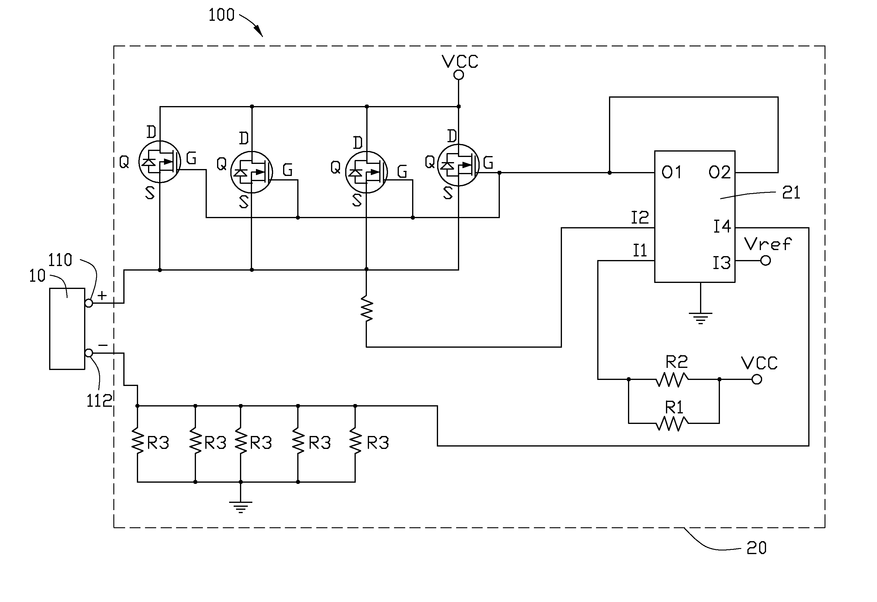
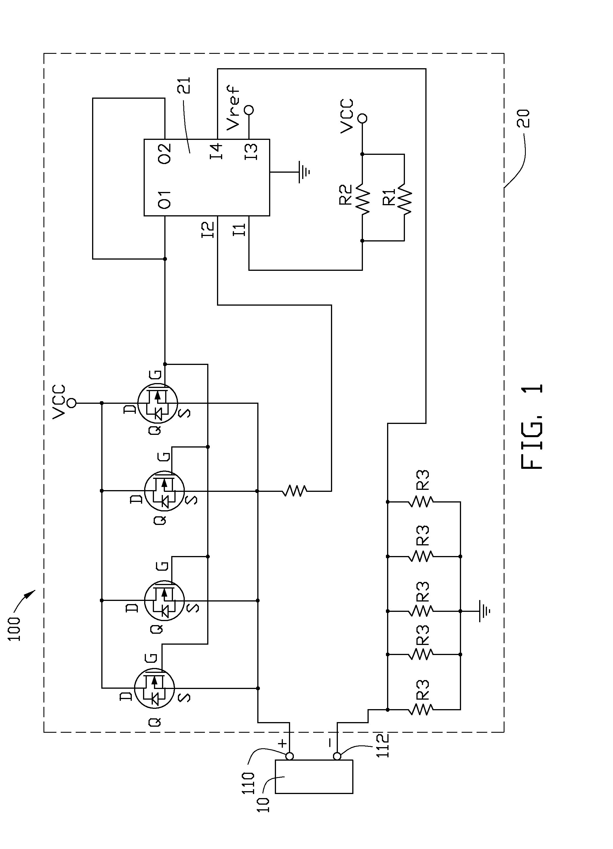
[0010]Referring to FIGS. 1 to 2, a CPU cooling circuit 100 according to one embodiment of the present disclosure is shown. The CPU cooling circuit 100 includes a current source circuit 20 and a thermoelectric element 10 driven by the circuit 20. The circuit 20 controls a current output to the thermoelectric element 10 to cool a CPU (not shown) to which the thermoelectric element 10 is attached.

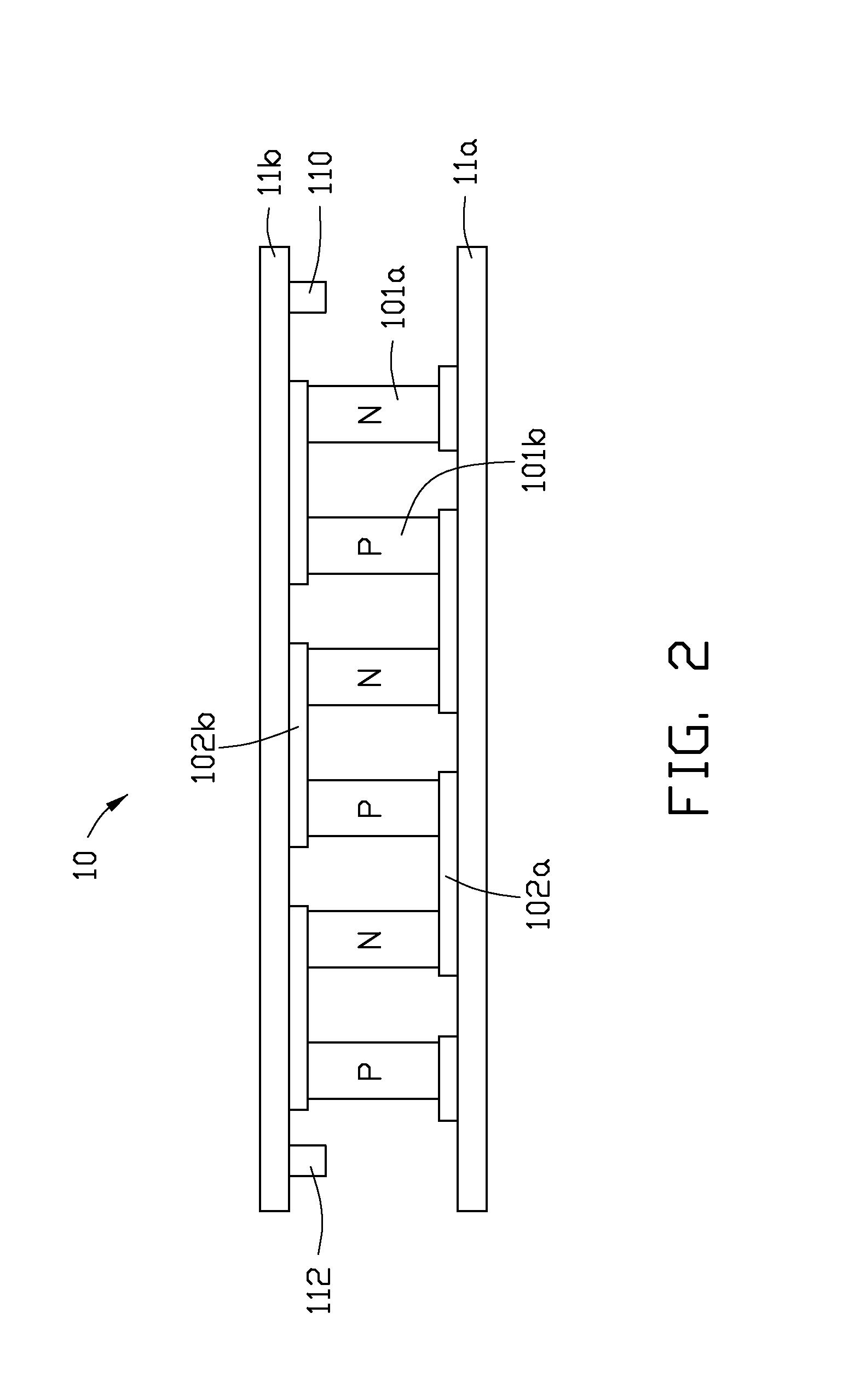
[0011]As shown in FIG. 2, the thermoelectric element 10 includes a first thermoelectric substrate 11a coupled to the CPU and an opposite second thermoelectric substrate 11b, a plurality of p-type semiconductor units 101a, and a plurality of n-type semiconductor units 101b. The thermoelectric element 10 further includes a first electrically conductive pattern 102a and a second electrically conductive pattern 102b ...


PUM


Abstract

A CPU cooling circuit for a CPU includes a thermoelectric element and a current source circuit. The thermoelectric element includes a first thermoelectric substrate attached to the CPU, a second thermoelectric substrate opposite to the first thermoelectric substrate, a plurality of n-type semiconductor units and p-type semiconductor units alternately sandwiched between the first and the second thermoelectric substrates and electrically connected in series between a positive power supply input and a negative power supply input. The current source circuit is configured for providing driving current to flow through the n-type semiconductor units and the p-type semiconductor units of the thermoelectric element according to a temperature of the CPU.

Description

BACKGROUND[0001]1. Technical Field[0002]The present disclosure relates to a central processing unit (CPU) cooling circuit, and more particularly, to CPU cooling circuit having thermoelectric element.[0003]2. Description of Related Art[0004]During operation of an electronic element of an electronic device, such as a central processing unit (CPU) of a computer, a large amount of heat is often produced. The heat must be quickly removed from the CPU to prevent unstable operation or damage to the CPU. Typically, a heat sink made of aluminum or copper is attached to an outer surface of the CPU to absorb the heat from the CPU. The heat absorbed by the heat sink is then dissipated to the ambient air via a fan attached on the heat sink. However, dissipating heat to air is slow and inefficient. In addition, when the temperature of the CPU is high, the fan will keep operating at a high-speed of rotation, which wastes electric power and shortens the life of the fan.[0005]Therefore, a new system...

Claims


Application Information

Patent Timeline
IPC IPC(8): F25B21/02
CPCG06F1/20H01L23/38H01L2924/0002H01L2924/00
Inventor ZHOU, HAI-QINGTONG, SONG-LIN
Owner HONG FU JIN PRECISION IND (SHENZHEN) CO LTD
Learn More