Cable gland and gasket ring assembly

a technology of gasket ring and cable gland, which is applied in the direction of electrical apparatus casing/cabinet/drawer, coupling device connection, metal-working hand tools, etc., can solve the problems of accidental fall of rubber o-ring or rubber pad from the cable gland, insufficient leakage protection, etc., and achieve the effect of protecting against moisture and dus

Active Publication Date: 2011-09-22
AVC INDAL CORP
View PDF17 Cites 27 Cited by
  • Summary
  • Abstract
  • Description
  • Claims
  • Application Information

AI Technical Summary

Benefits of technology

[0010]The present invention has been accomplished under the circumstances in view. It is therefore the main object of the present invention to provide a cable gland and gas...

Problems solved by technology

After installation of a cable in a junction box by means of a cable gland, the cable may be disconnected or loosened from the connector or gland when stretched accidentally by an external force, causing leakage.
When the rubber O-ring or rubber pad is sandwiched between the cable gland and the junction box of the signal source or signal receiver, it tends to be stretched or excessively deformed, leading in insufficient leakage protection....

Method used


Image

  • Cable gland and gasket ring assembly
  • Cable gland and gasket ring assembly
  • Cable gland and gasket ring assembly

Examples


Embodiment Construction

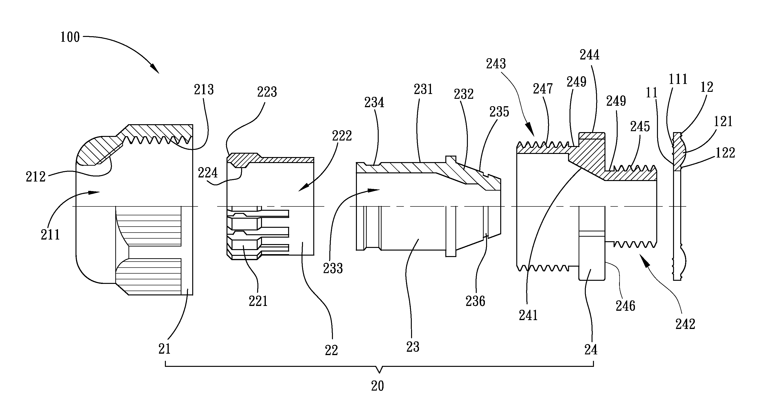
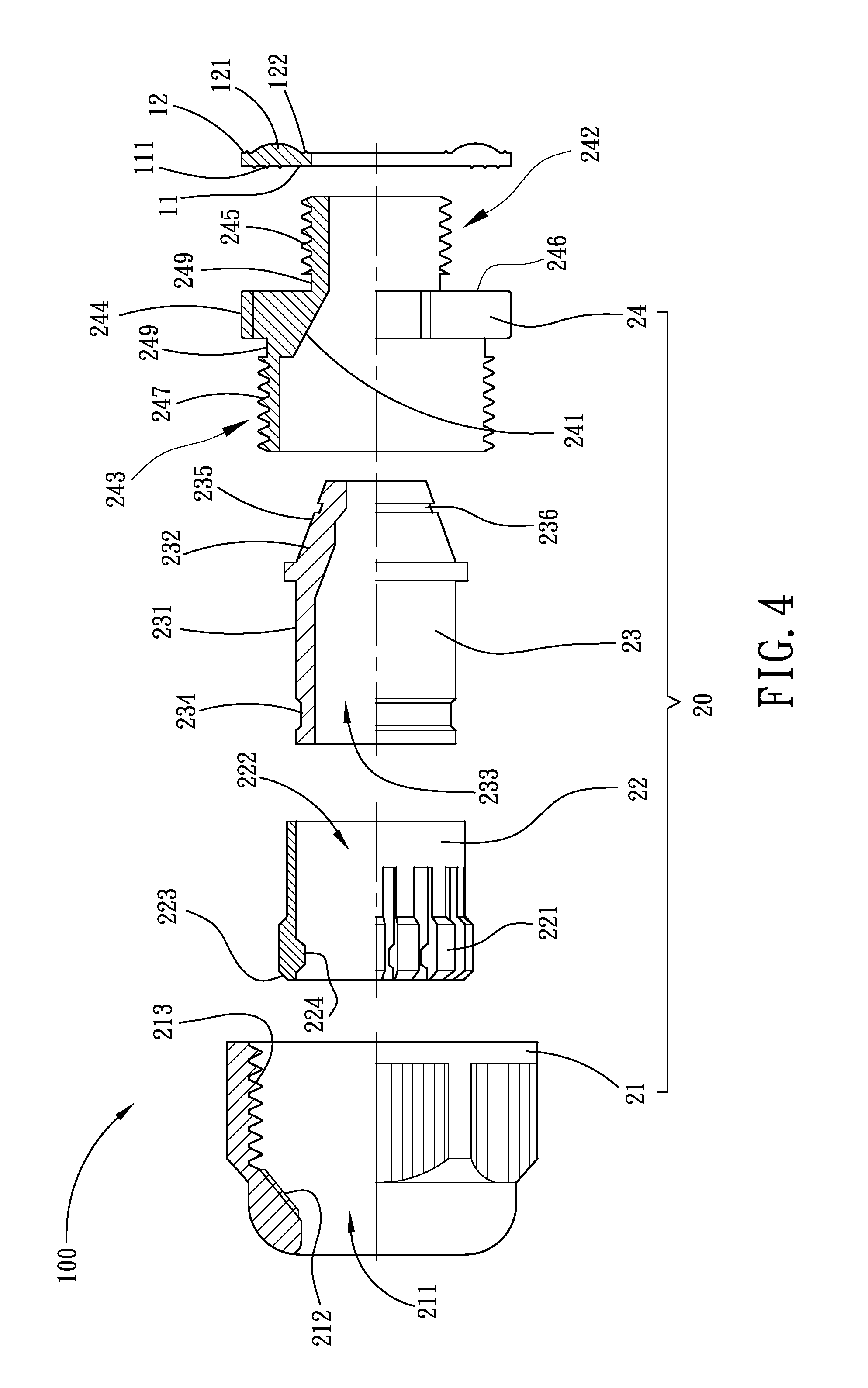
[0037]Referring to FIGS. 1˜5, a cable gland and gasket ring assembly 100 in accordance with a first embodiment of the present invention is shown comprising a gasket ring 10 and a cable gland 20.

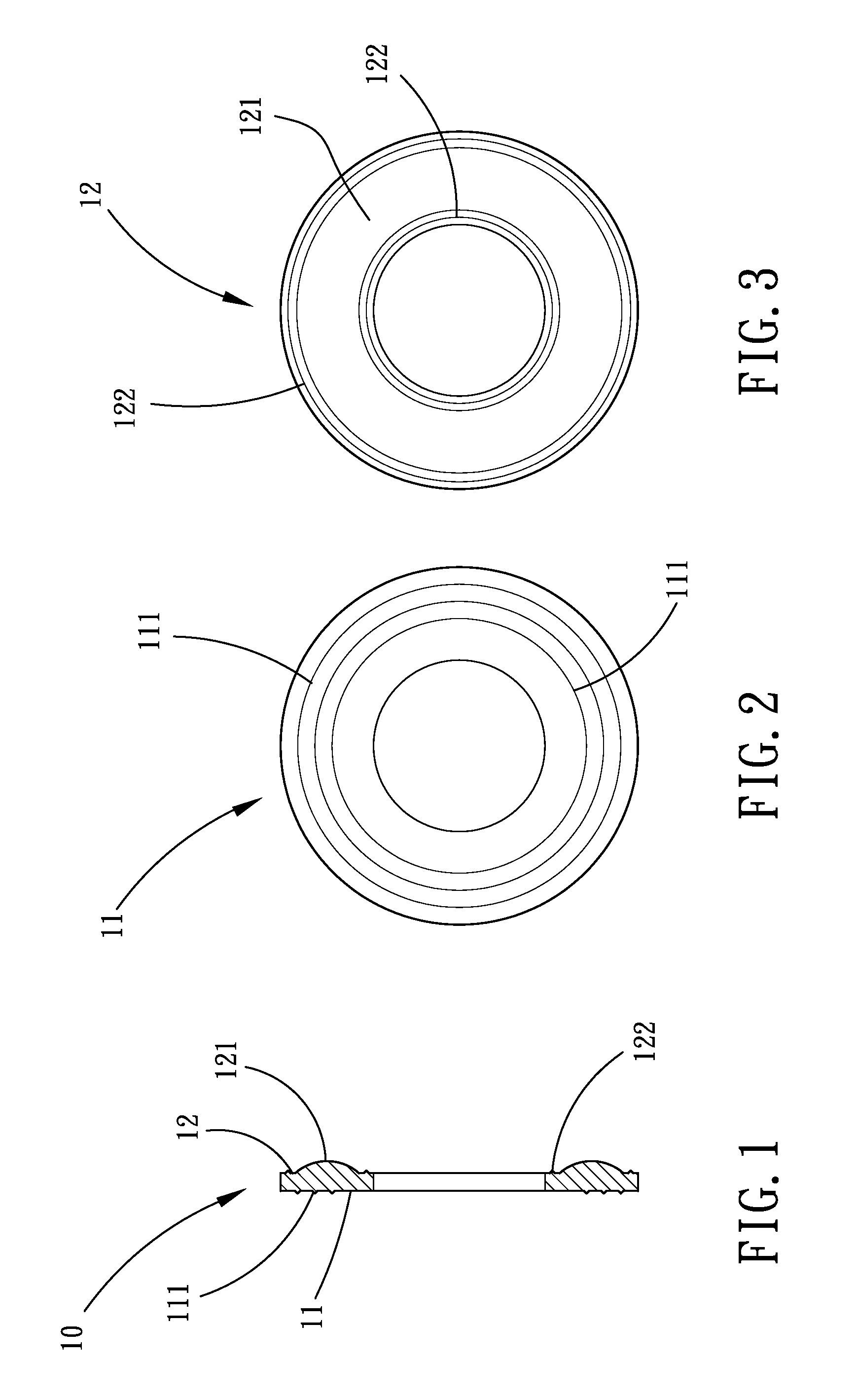
[0038]Referring to FIGS. 1 and 3, the gasket ring 10 is prepared from an elastically deformable material, for example, rubber, defining along the axis thereof a first end face 11 and a second end face 12 opposing the first end face 11. The first end face 11 has a plurality of concentrically arranged annular ribs 111. The second end face 12 has an annular convex portion 121 and at least one annular rib 122 surrounded by the annular convex portion 121.

[0039]Referring to FIGS. 4 and 7, the cable gland 20 comprises a shell 21, a collar 22, a packing ring 23 and a connection ring 24. The connection ring 24 is a tubular member comprising a stop flange segment 244 located on the middle, a first connection ring segment 242 axially extended from one side of the stop flange segment 244, a second connec...


PUM

PropertyMeasurementUnit
Flexibilityaaaaaaaaaa

Abstract

A cable gland and gasket ring assembly includes a gasket ring and a cable gland formed of a shell, a collar, a packing ring and a connection ring for securing a cable, or, a cable and a flexible conduit, to a junction box. The gasket ring is an annular member, having a first end face, a second end face opposing the first end face, a plurality of annular ribs concentrically arranged on the first end face and an annular convex portion located on the second end face. The connection ring has a stop flange segment, a first connection ring segment extended from one side of the stop flange for holding the gasket ring, an outer thread located on the first connection ring segment for fastening to a junction box, a recessed portion on the stop flange segment for receiving the annular convex portion of the gasket ring and a tapered inner surface located on the inside of the stop flange segment for stopping against a tapered outside surface of the packing ring.

Description

BACKGROUND OF THE INVENTION[0001]1. Field of the Invention[0002]The present invention relates to cable glands and more particularly, to a cable gland and gasket ring assembly, which effectively prohibits access of dust and water particles to the inside of the junction box after installation of a cable with the cable bland in the junction box.[0003]2. Description of the Related Art[0004]After installation of a cable in a junction box by means of a cable gland, the cable may be disconnected or loosened from the connector or gland when stretched accidentally by an external force, causing leakage. To avoid this problem, an improved design of cable gland is disclosed. This prior art design of cable gland comprises a first shell, a packing ring, a sealing nut, a lock nut, a connection ring, an inner retaining ring, an elastic ring and a second shell. After installation, the packing ring is forced to wrap about the cable tightly, thereby locking the cable and protecting against moisture.[0...

Claims


Application Information

Patent Timeline
IPC IPC(8): F16C1/10
CPCF16C1/102F16C1/262H02G3/0641Y10T74/2045F16C1/107Y10T74/20462Y10T403/4682H02G3/0675F16B2200/403H02G3/0691
Inventor CHIOU, JIUN WEI
Owner AVC INDAL CORP
Why Eureka
Try Eureka