Shock reduction muzzle brake

a technology of shock reduction and muzzle brake, which is applied in the field of large caliber weapons, can solve the problems of decompression shock on the projectile, damage to electronic components, and prevent them from performing, and achieve the effects of reducing base decompression shock, reducing decompression shock, and increasing decompression tim

Active Publication Date: 2011-09-22
RAYTHEON CO
View PDF8 Cites 14 Cited by
  • Summary
  • Abstract
  • Description
  • Claims
  • Application Information

AI Technical Summary

Benefits of technology

[0007]Unlike current muzzle brake designs that reflect shock waves back onto the projectile, the present invention minimizes or eliminates these reflected shock waves. The muzzle brake provided by the invention also reduces base decompression shock on the back (base) of the projectile by increasing the decompression time and thus decreasing the magnitude of the shock wave impacting the projectile from behind as it exits the gun barrel. Reducing the shock wave also reduces tip-off (pitch and yaw) by reducing unsymmetrical forces acting on the projectile. Like previous muzzle brakes, the muzzle brake provided by the invention also reduces the recoil force transmitted to the support structure by maintaining sufficient rearward-facing surface area in the path of the propellant gases to generate a force in a forward direction to counter the rearward-acting recoil forces.
[0008]Unlike prior muzzle brakes, the shock reduction muzzle brake provided by the present invention directs the propellant gasses out of the muzzle brake without reflecting shock waves back onto the projectile as it travels through the muzzle brake. The propellant gasses enter the rear of the muzzle brake and as the gasses advance through the muzzle brake some of the gas is redirected outward and against sufficient surface area to maintain the recoil capability without reflecting the shock waves back inward into the muzzle brake and onto the projectile.
[0009]Prior muzzle brake designs also tend to use large openings that allow the pressure on the base of the projectile to decompress quickly. This creates a decompression shock on the projectile when the pressure is released. Rather than a few large openings, the muzzle brakes provided by the invention have a multitude of smaller openings so that the propellant gases are exhausted more slowly and the pressure is reduced more gradually without a sudden shock.

Problems solved by technology

These electronic components are more sensitive to shock waves, which can damage the electronic components and prevent them from performing in their intended manner.
This creates a decompression shock on the projectile when the pressure is released.

Method used


Image

  • Shock reduction muzzle brake
  • Shock reduction muzzle brake
  • Shock reduction muzzle brake

Examples


Embodiment Construction

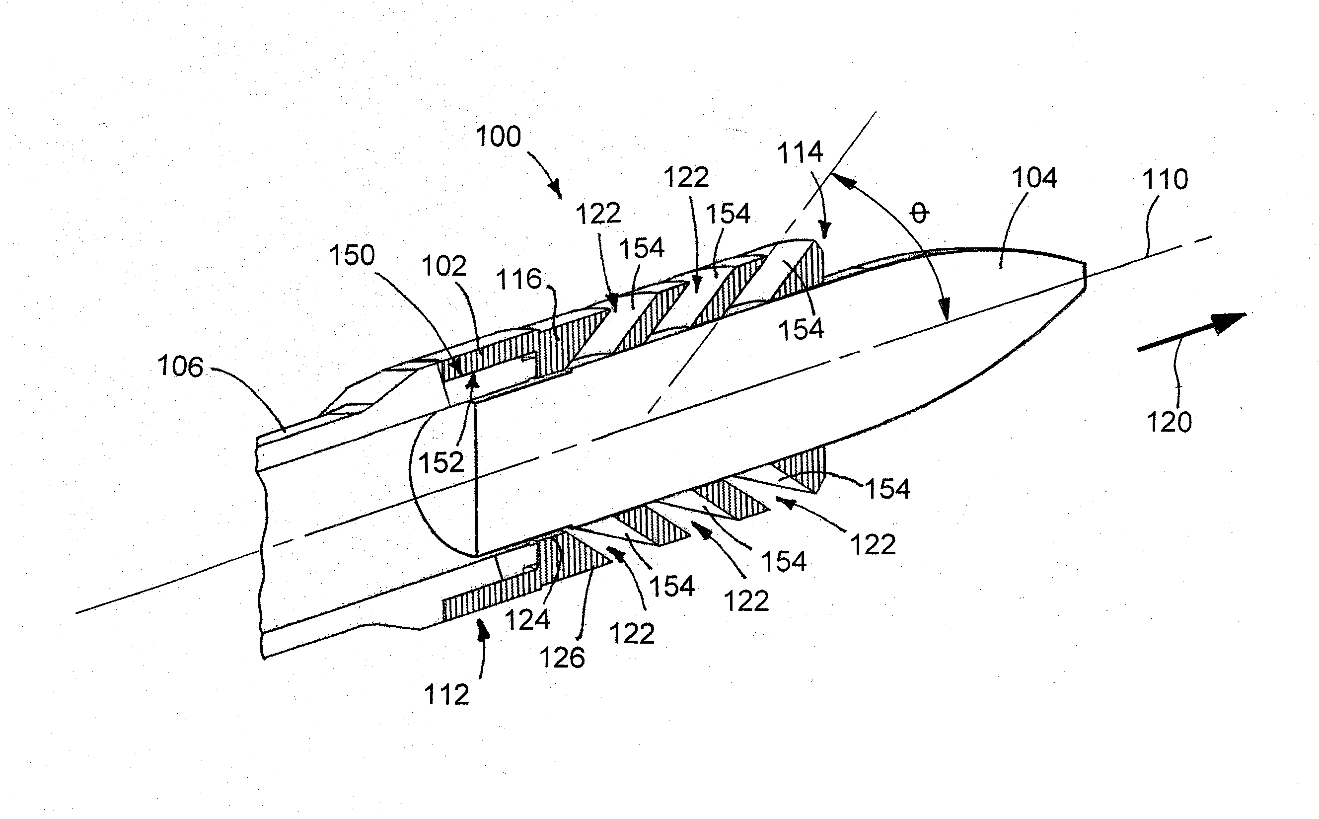
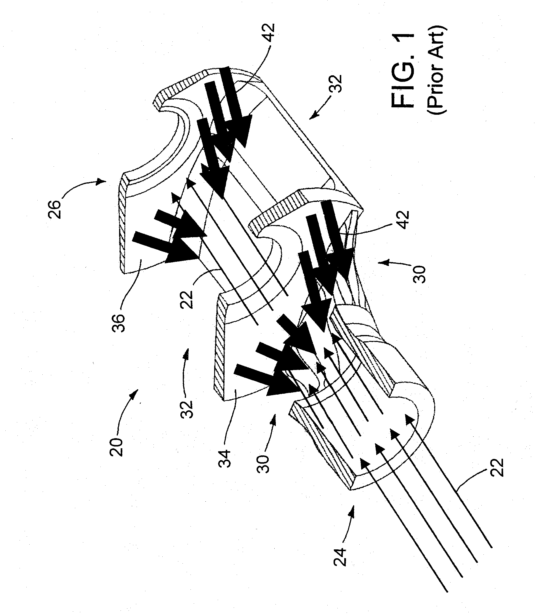
[0026]Turning now to the drawings and a detailed description of exemplary embodiments of the invention, our invention provides a shock reduction muzzle brake 100 (FIG. 5) that generates a reaction force to counter recoil forces, while also minimizing or eliminating the shock waves and related effects created by prior muzzle brake designs. Prior muzzle brake designs often reflect shock waves back onto the projectile as it passes through the muzzle brake and also vent propellant gases so rapidly that the decompression effects on the base of the projectile can damage the electronic components of a smart projectile. The muzzle brakes provided by the invention have multiple, relatively small propellant gas exhaust ports that vent the pressurized propellant gases relatively slower to reduce the rate of decompression on the base of the projectile, and the propellant gas exhaust ports are forwardly-inclined to direct shock waves away from the path of the projectile.

[0027]As mentioned above,...


PUM


Abstract

A shock reduction muzzle brake 100 for the muzzle end of a gun barrel 106 (i) maintains sufficient rearward-facing surface area in the path of the expanding propellant gas to counter the recoil, while also (ii) guiding shock waves away from a path of a projectile 104 and (iii) decreasing the rate of base decompression to minimize decompression shock. The muzzle brake 100 includes (a) a tube 102 that defines a path for a projectile 104, and (b) multiple forwardly-inclined holes 122 extending through the side wall 116 of the tube 102 to divert propellant gases away from the path of the projectile 104. The forwardly-inclined holes 122 have an outlet of that is closer to the forward end 114 of the tube 102 than the inlet of the hole 122, thereby limiting the surface area that could reflect shock waves back onto the projectile 104. The holes 122 are sized to slow release of the base pressure to minimize decompression shock.

Description

FIELD OF THE INVENTION[0001]This invention relates to the field of large caliber weapons, particularly artillery weapons, where recoil forces are a major concern. More specifically, the invention relates to muzzle brakes as applied to large caliber guns and to the use of those brakes in the control of recoil forces during firing.BACKGROUND[0002]Large caliber weapons deliver relatively large, heavy projectiles at relatively high velocities to distant targets. When the weapon is fired, a propellant burns and hot gasses rapidly expand in volume inside a gun barrel. The expanding gases accelerate a projectile along the length of the tubular barrel, ejecting the projectile at a high velocity from the muzzle end of the barrel. The expanding propellant gasses follow the projectile and are expelled into the atmosphere at velocities equaling or even exceeding those of the projectile, similar to an exhaust plume from a rocket. The combination of accelerating the projectile and the propellant ...

Claims


Application Information

Patent Timeline
Patent Type & Authority Applications(United States)
IPC IPC(8): F41A21/36
CPCF41A21/36
Inventor PETERSON, WILLIAM S.OFFOLTER, MATTHEW A.
Owner RAYTHEON CO
Why Eureka
Try Eureka