Electronic earplug with transistor switching for introducing electronic control of the gain and providing audible switch indications

a transistor switching and electronic ear plug technology, applied in the direction of ear plugs, ear treatment, earmuffs, etc., can solve the problems of high risk of hearing loss for military personnel exposed to firearm blasts, explosions and other high-level peak noises, 68% of deployed soldiers returning with ear damage, and 100% do not protect both ears

Active Publication Date: 2011-09-22
ETYMOTIC RES
View PDF6 Cites 51 Cited by
  • Summary
  • Abstract
  • Description
  • Claims
  • Application Information

AI Technical Summary

Benefits of technology

[0053]These and other advantages, aspects and novel features of the present invention, as well as details of illustrative aspects thereof, will be more fully understood from the following description and drawings.

Problems solved by technology

It is highly documented that military personnel exposed to blasts from firearms, explosions and other high level peak noises are at high risk for hearing loss.
It has been estimated that 68% of deployed soldiers return with ear damage, and 100% do not protect both ears during combat.
Exposure to the peak noises caused by gunfire or other explosions adds hearing loss to the long list of risks and dangers encountered by soldiers on the battle field.
Thus, softer sounds that would otherwise be audible without the use of earplugs may become inaudible or become so soft that they go unnoticed.
For example, a soldier wearing earplugs as described attenuating a constant 40 dB of noise may fail to hear an enemy quietly approaching or fail to perceive communications from fellow soldiers.
Likewise, a construction worker wearing such earplugs may receive adequate protection from high level construction sounds, but fail to hear a distant coworker's emergency call for help.
Many earplugs, like those described by Gardner, for example, may distort the reception of normal sound.
The earplugs attenuate higher frequency sounds at a higher level than lower frequency sounds making it difficult for the wearer to hear or understand speech and other important sounds.
While the high audibility of these earplugs allows the wearer to hear softer noises, they may not provide adequate protection for extremely high level sounds.
Moreover, even the lowest-attenuation ER-9 earplug may produce unacceptable attenuation for a soldier who needs to have the best chance of hearing a quietly approaching enemy.
Moreover 9 dB attenuation is insufficient to protect the soldier's ears from many high-energy noise levels that occur during battle.
The Combat Arms Earplug introduces less noise attenuation for external SPLs below 110 dB than for external SPLs above 110 dB, but does not provide a constant attenuation across all frequencies.
It seems clear from the refusal of soldiers to wear existing hearing protection that no existing devices provide the combination of situational awareness (especially for quiet sounds) and blast protection that is needed.
They all have in common that they use a tiny hearing aid receiver whose maximum output of 110-125 dB is further limited by a limited power available from the output amplifier in the hearing aid.
The K-AMP Hearing Aid had the advantage that it provided normal localization for the hunter and near-normal “situational awareness,” but a drawback was that it had to be built into a custom earmold shell which typically required 2-3 visits to a licensed hearing aid dispenser.
The problem with all present devices is that they do not provide a low-cost, ready-to-wear, high-fidelity device with a 16 kHz bandwidth, suitable for the normal-hearing soldier.

Method used


Image

  • Electronic earplug with transistor switching for introducing electronic control of the gain and providing audible switch indications
  • Electronic earplug with transistor switching for introducing electronic control of the gain and providing audible switch indications
  • Electronic earplug with transistor switching for introducing electronic control of the gain and providing audible switch indications

Examples


Embodiment Construction

)

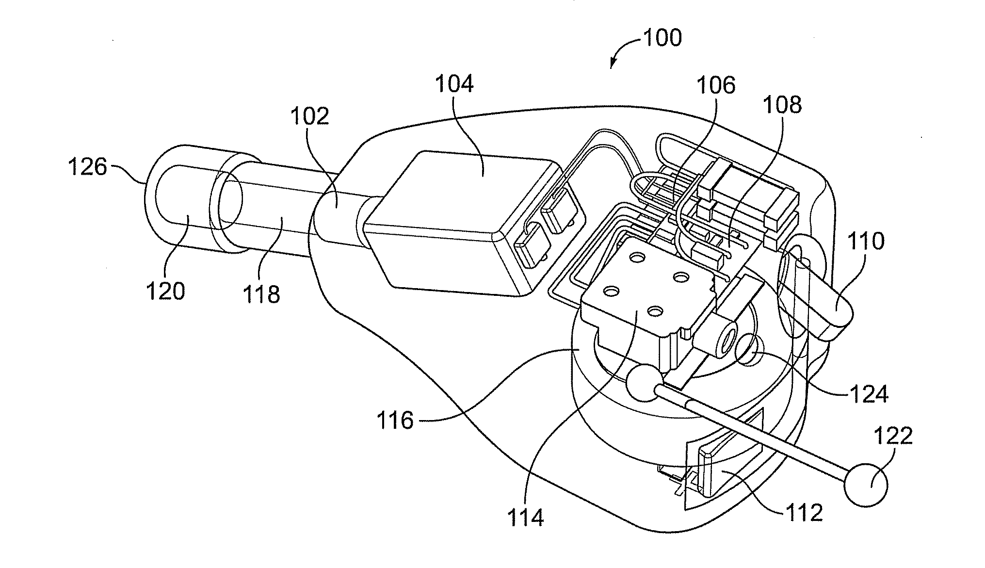
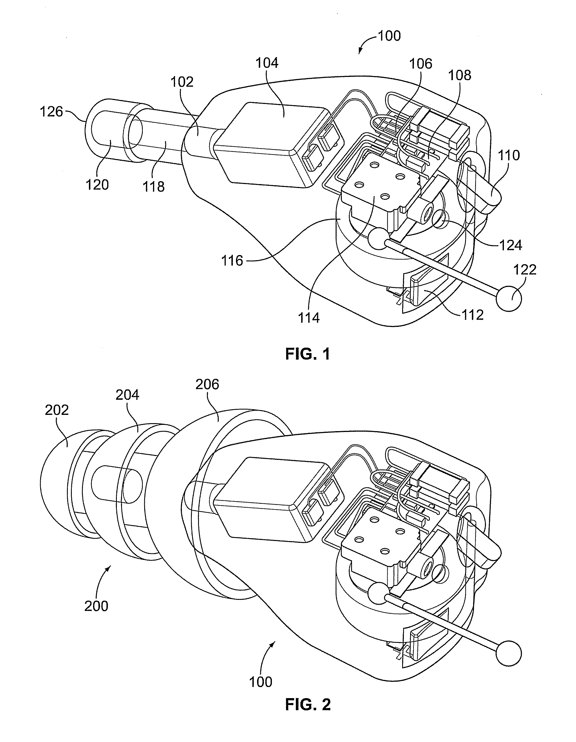
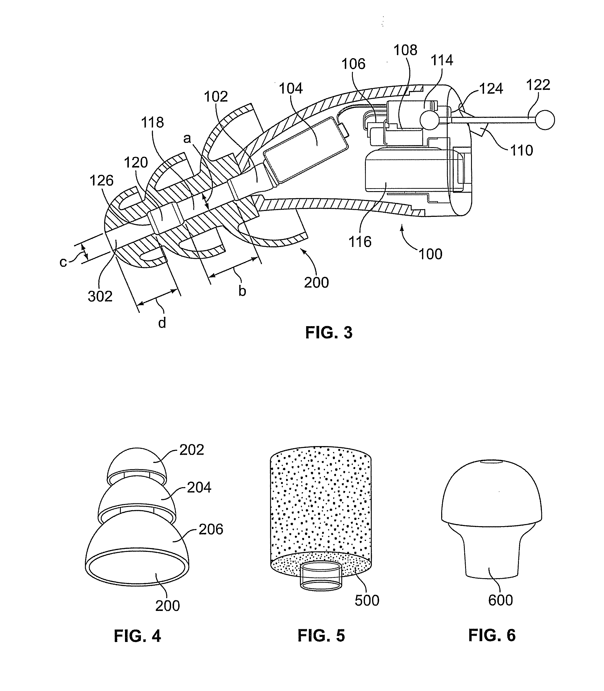
[0092]Embodiments of the present technology provide electronic earplugs, methods of enhancing and / or attenuating sound using electronic earplugs, and kits including electronic earplugs. Embodiments of the present technology further provide transistor switching for introducing electronic control of the gain of electronic earplugs and providing audible switch indications when switching between gain level settings.

[0093]The realization that it would be practical to make such a device came partly from considering experiments performed at the request of applicant's company by E-A-R Cal Laboratories. These experiments found that the attenuation of both foam eartips and triple-flange eartips, when combined with a miniature insert earphone such as the Etymotic ER-4 or ER-6i, was equal to or perhaps a dB or so greater than the attenuation of the foam or triple-flange eartip itself (which is normally manufactured without the sound channel down through the middle). Thus with the applicant's w...


PUM


Abstract

Electronic earplugs, methods of enhancing and/or attenuating sound using electronic earplugs, and kits including electronic earplugs are provided. Certain electronic earplugs may include a circuit operatively connected to a microphone. The circuit may be configured to receive input electrical signals from the microphone and provide output electrical signals to a receiver. Further, the circuit may be configured to modify a sound output level from the electronic earplug based on a sound input level of ambient sound received at the microphone and a gain characteristic setting selected from a plurality of gain characteristic settings. The circuit may be configured such that it can be switched between the plurality of gain characteristic settings, wherein the switching to the selected gain characteristic setting produces an audible switch indication. Certain electronic earplugs also include a receiver configured to convert the output electrical signals into sound that is communicated to a user's ear canal.

Description

CROSS-REFERENCE TO RELATED APPLICATIONS / INCORPORATION BY REFERENCE[0001]The present application is a continuation-in-part and claims priority under 35 U.S.C. §120 to copending U.S. patent application Ser. No. 12 / 914,314, filed on Oct. 28, 2010, which claims priority under 35 U.S.C. §119(e) to the following U.S. Provisional Applications: 61 / 256,807 filed on Oct. 30, 2009, entitled Electronic Earplug; 61 / 298,755 filed on Jan. 27, 2010, entitled Electronic Earplug; 61 / 299,232 filed on Jan. 28, 2010, entitled Two-Way Communication Device With Multiple Microphones; 61 / 313,201 filed on Mar. 12, 2010 entitled, Telecoil Option For Electronic Blast Plug And Quiet Sound Amplifier Products; and 61 / 386,344 filed on Sep. 24, 2010 entitled Wireless Two-Way Communication Device Using A Single Coil. The entire contents of each above-mentioned prior-filed application is hereby expressly incorporated herein by reference.[0002]U.S. Pat. No. 4,592,087 issued to Killion on May 27, 1986, is incorporated ...

Claims


Application Information

Patent Timeline
Patent Type & Authority Applications(United States)
IPC IPC(8): A61F11/06
CPCA61F2011/145A61F11/08A61F11/145
Inventor KILLION, MEAD C.MATZEN, NORMAN P.
Owner ETYMOTIC RES
Why Eureka
Try Eureka