
Method and Apparatus for Mirroring Frames to a Remote Diagnostic System

a diagnostic system and remote diagnostic technology, applied in the field of frame mirroring, can solve the problems of increasing diagnostic difficulty, increasing diagnostic difficulty, and increasing the complexity of effective deployment of multiple devices in the network environmen

Active Publication Date: 2011-09-22
AVAGO TECH INT SALES PTE LTD
View PDF19 Cites 81 Cited by
  • Summary
  • Abstract
  • Description
  • Claims
  • Application Information

AI Technical Summary

Benefits of technology

[0006]One or more embodiments according to the invention relate to remote port mirroring, which includes apparatuses and methods to mirror frames received at an input port or provided by an output port to a port not connected to the device performing the mirroring operation. A frame being sent to the diagnostic system has a mirror header added to allow the frame to be routed through any intervening switches in the same fabric to the diagnostic device. Either the final switch or the diagnostic system removes the mirror header and then the diagnostic system can analyze the mirrored frame as needed. If the diagnostic system is attached in a different fabric, encapsulation and inter-fabric routing headers are added as needed to the frame containing the mirror header. This allows the frame to traverse multiple fabrics to reach the diagnostic system. The encapsulation and inter-fabric routing headers are removed as done normally, leaving only the mirror header for routing in the final fabric. This allows a diagnostic system to be connected to any switch in the network, either in the same or a different fabric.

Problems solved by technology

Effectively deploying multiple devices in a network environment becomes an increasingly complex task as transmission data rates, processor speeds, and storage capacities increase.
At these rates diagnostics become very difficult.
This makes simple trace capture inside the switch difficult as the needed memory could easily exceed that needed for normal switch operations.
This makes connection of a conventional protocol analyzer troublesome in many instances.
However, this approach has been limited because of a requirement that the diagnostic system be directly connected to the switch performing the mirroring.
While better than being required to be in series, this direct connection requirement still limited the flexibility of the SAN configuration unduly, requiring reconfiguration should the diagnostic system not be connected to one of the necessary switches, assuming that the switches can perform the mirror approach.

Method used


Image

  • Method and Apparatus for Mirroring Frames to a Remote Diagnostic System
  • Method and Apparatus for Mirroring Frames to a Remote Diagnostic System
  • Method and Apparatus for Mirroring Frames to a Remote Diagnostic System

Examples


Embodiment Construction

[0015]Reference will now be made in detail to several embodiments of the invention, examples of which are illustrated in the accompanying drawings. Reference in the specification to “one embodiment” or to “an embodiment” means that a particular feature, structure, or characteristic described in connection with the embodiments is included in at least one embodiment of the invention. The appearances of the phrase “in one embodiment” in various places in the specification are not necessarily all referring to the same embodiment. Wherever practicable, the same reference numbers will be used throughout the drawings to refer to the same or like parts.

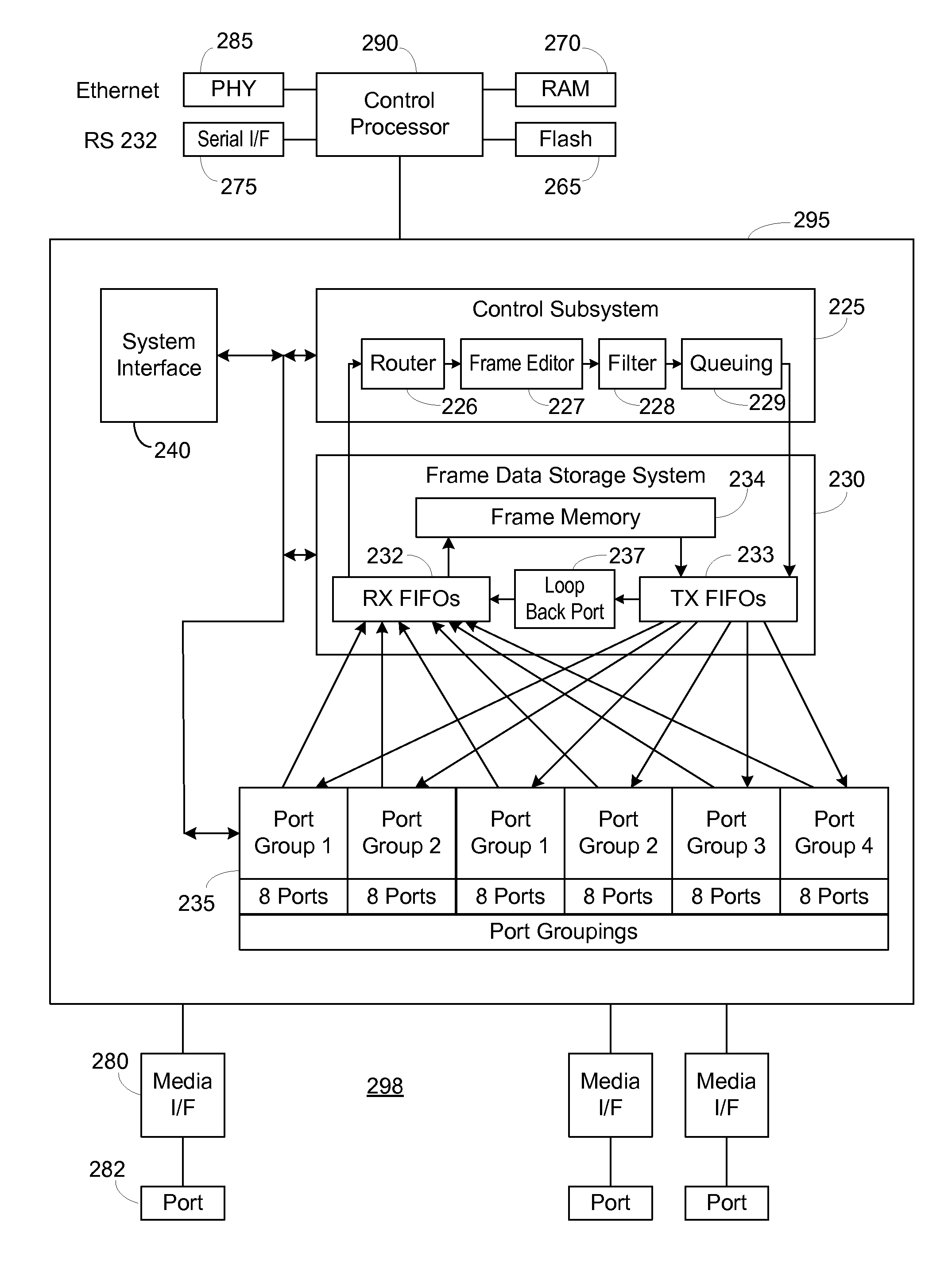
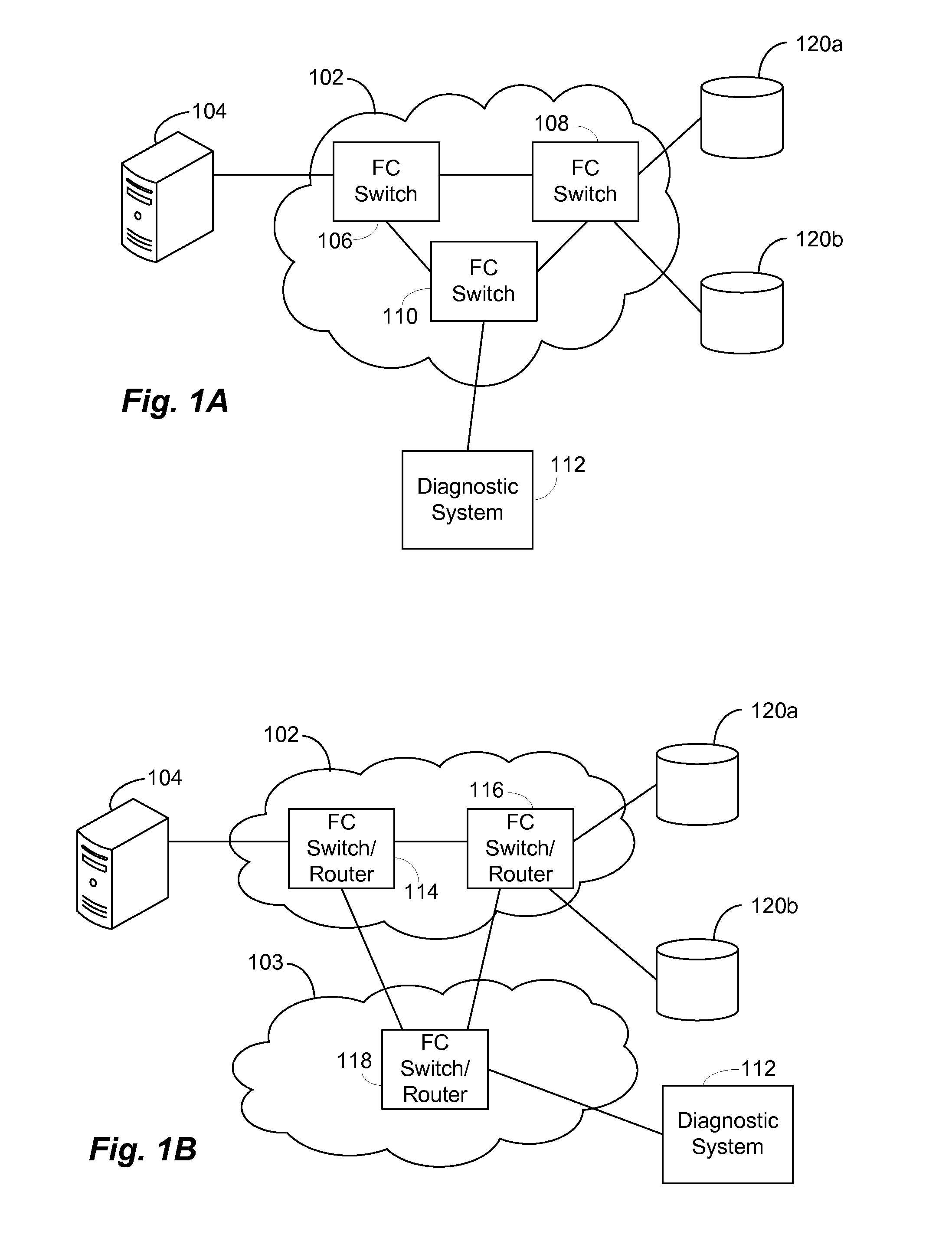
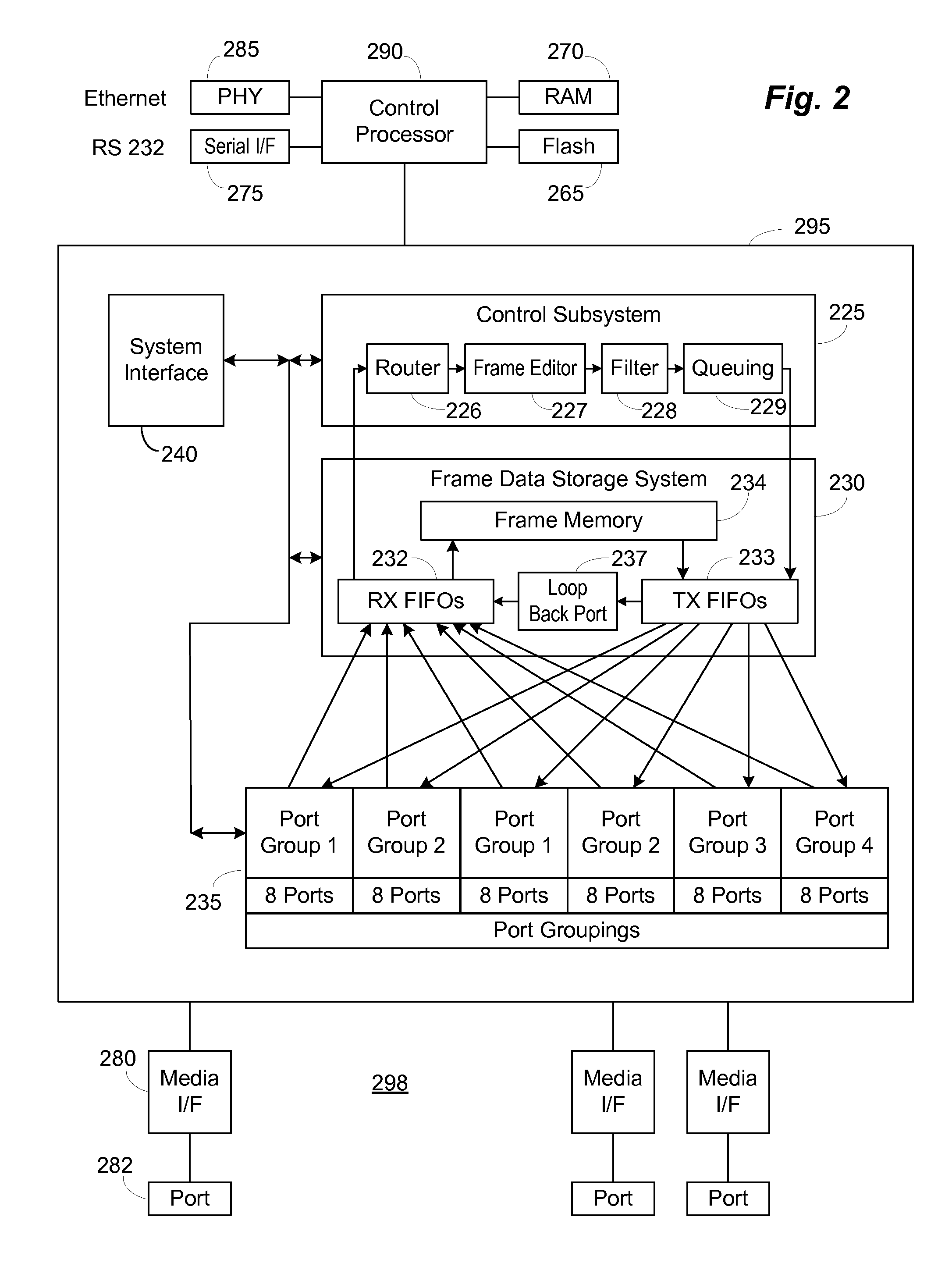
[0016]FIG. 1A shows components in a network 100. A fabric 102 includes interconnected Fibre Channel (FC) switches 106, 108, 110 according to the present invention. A host 104 is connected to FC switch 106. One or more storage devices 120a, 120b are illustrated as connected to FC switch 108. A diagnostic system 112 is connected to FC switch 11...


PUM


Abstract

Apparatuses and methods to mirror frames received at an input port or provided by an output port to a port not connected to the device performing the mirroring operation. A frame being sent to a diagnostic system has a mirror header added to allow the frame to be routed through any intervening switches in the same fabric. The final switch or the diagnostic system removes the mirror header. If the diagnostic system is attached in a different fabric, encapsulation and inter-fabric routing headers are added as needed to the frame containing the mirror header. This allows the frame to traverse multiple fabrics to reach the diagnostic system. The encapsulation and inter-fabric routing headers are removed as done normally. This allows a diagnostic system to be connected to any switch in the network, either in the same or a different fabric.

Description

BACKGROUND OF THE INVENTION[0001]1. Field of the Invention[0002]Embodiments according to the invention relate to a method and apparatus for frame mirroring in a network environment. More particularly, embodiments according to the invention relate to mirroring frames to a diagnostic system not connected to the device performing the mirror operation.[0003]2. Description of the Related Art[0004]Effectively deploying multiple devices in a network environment becomes an increasingly complex task as transmission data rates, processor speeds, and storage capacities increase. Storage area networks (SANs) have been developed as specialized high-speed networks, referred to as fabrics, to connect computer systems, control software, and storage devices over the fabric. A SAN typically allows block level input / output (I / O) rather than file-level access. Thus, every device connected to a SAN fabric appears as a locally attached device to other devices on the fabric.[0005]Data rates of the switche...

Claims


Application Information

Patent Timeline
Patent Type & Authority Applications(United States)
IPC IPC(8): G06F15/16
CPCH04L43/12H04L12/4633
Inventor ALTEKAR, SATSHEEL BHASKERBALAKAVI, VENKATA PRAMODKO, KUNG-LINGVARANASI, SURYA PRAKASH
Owner AVAGO TECH INT SALES PTE LTD
Learn More