Mask and method for use in respiratory monitoring and diagnostics

a mask and mask technology, applied in the field of masks and methods for respiratory monitoring and diagnostics, can solve the problems of excessive daytime sleepiness, disturbed sleep patterns of respiratory disorders, and restless sleep

Inactive Publication Date: 2011-04-21
UNIV HEALTH NETWORK
View PDF13 Cites 45 Cited by
  • Summary
  • Abstract
  • Description
  • Claims
  • Application Information

AI Technical Summary

Benefits of technology

[0039]Other aims, objects, advantages and features of the invention will become more apparent upon reading of the following non-restrictive description of specific embodiments thereof, given by way of example only with reference to the accompanying drawings.

Problems solved by technology

Also, respiratory disorders are known to disturb sleep patterns.
For example, recurrent apneas and hypopnea lead to intermittent hypoxia that provokes arousals and fragmentation of sleep, which in turn may lead to restless sleep, and excessive daytime sleepiness.
Repetitive apneas and intermittent hypoxia may also elicit sympathetic nervous system activation, oxidative stress and elaboration of inflammatory mediators which may cause repetitive surges in blood pressure at night and increase the risk of developing daytime hypertension, atherosclerosis, heart failure, and stroke independently from other risks.
Namely, while some have proposed diagnostic tools and methods for diagnosing, monitoring and / or generally investigating certain breathing disorders, these tools and methods are often particularly invasive and / or uncomfortable for the subject at hand, and therefore, can yield unsatisfactory results.
For instance, many diagnostic procedures are solely implemented within a clinical environment, which amongst other deficiencies, do not allow for monitoring a subject in its natural environment, leading to skewed or inaccurate results, or in the least, forcing the subject through an unpleasant and mostly uncomfortable experience.
Unfortunately, subject-driven electrode positioning and installation often leads to a reduction in subject comfort and compliance, and increases the chance that the electrodes will be detached or displaced in use.
Since accurate positioning and installation of such electrodes are paramount to proper diagnostics, captured signals in such situations are often unreliable, a measure which can only effectively be determined once the data is transferred back to a health center, at which point, such data, if properly identified, must be withdrawn from the study.
Furthermore, such devices regularly need to be shipped back to the health center for processing and, given their generally invasive nature, for hygienic reconditioning, e.g. disinfection.
Similarly, in a clinical setting, while the positioning and attachment of monitoring electrodes may be completed by an experienced health care professional, the devices currently used in such settings generally at best leave the subject physically wired to one or more monitoring devices, if not via more invasive techniques, which wiring can be a particular nuisance to the subjects general comfort and mobility, and obtrusive to individuals or health care practitioners maneuvering around the subject.
While these latter devices may be less dependent on subject positioning, they are equally limited in the type of data acquired for processing, as only one of airflow or sound can be accessed by any one of these designs.
Furthermore, each of the above examples proposes a configurationally limited design that generally suffers from various deficiencies which, in operation, limit its effectiveness in capturing accurate and usable data.
Furthermore, improvements and / or alternative approaches in the type and quality of information collected in monitoring and / or diagnosing a subject, as well as in the methods and procedures implemented in processing and analyzing this information are needed to yield better results without, for example, necessarily requiring further data diversity which, ultimately, can result in greater constraints to the subject's mobility and / or comfort.

Method used


Image

  • Mask and method for use in respiratory monitoring and diagnostics
  • Mask and method for use in respiratory monitoring and diagnostics
  • Mask and method for use in respiratory monitoring and diagnostics

Examples


Embodiment Construction

[0071]It should be understood that the disclosure is not limited in its application to the details of construction and the arrangement of components set forth in the following description or illustrated in the drawings. The disclosure is capable of other embodiments and of being practiced or of being carried out in various ways. Also, it is to be understood that the phraseology and terminology used herein is for the purpose of description and should not be regarded as limiting. The use of “including,”“comprising,” or “having” and variations thereof herein is meant to encompass the items listed thereafter and equivalents thereof as well as additional items. Unless limited otherwise, the terms “connected,”“coupled,” and “mounted,” and variations thereof herein are used broadly and encompass direct and indirect connections, couplings, and mountings. In addition, the terms “connected” and “coupled” and variations thereof are not restricted to physical or mechanical or electrical connect...


PUM


Abstract

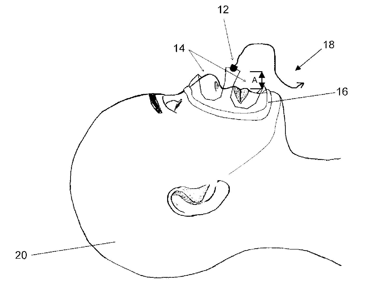
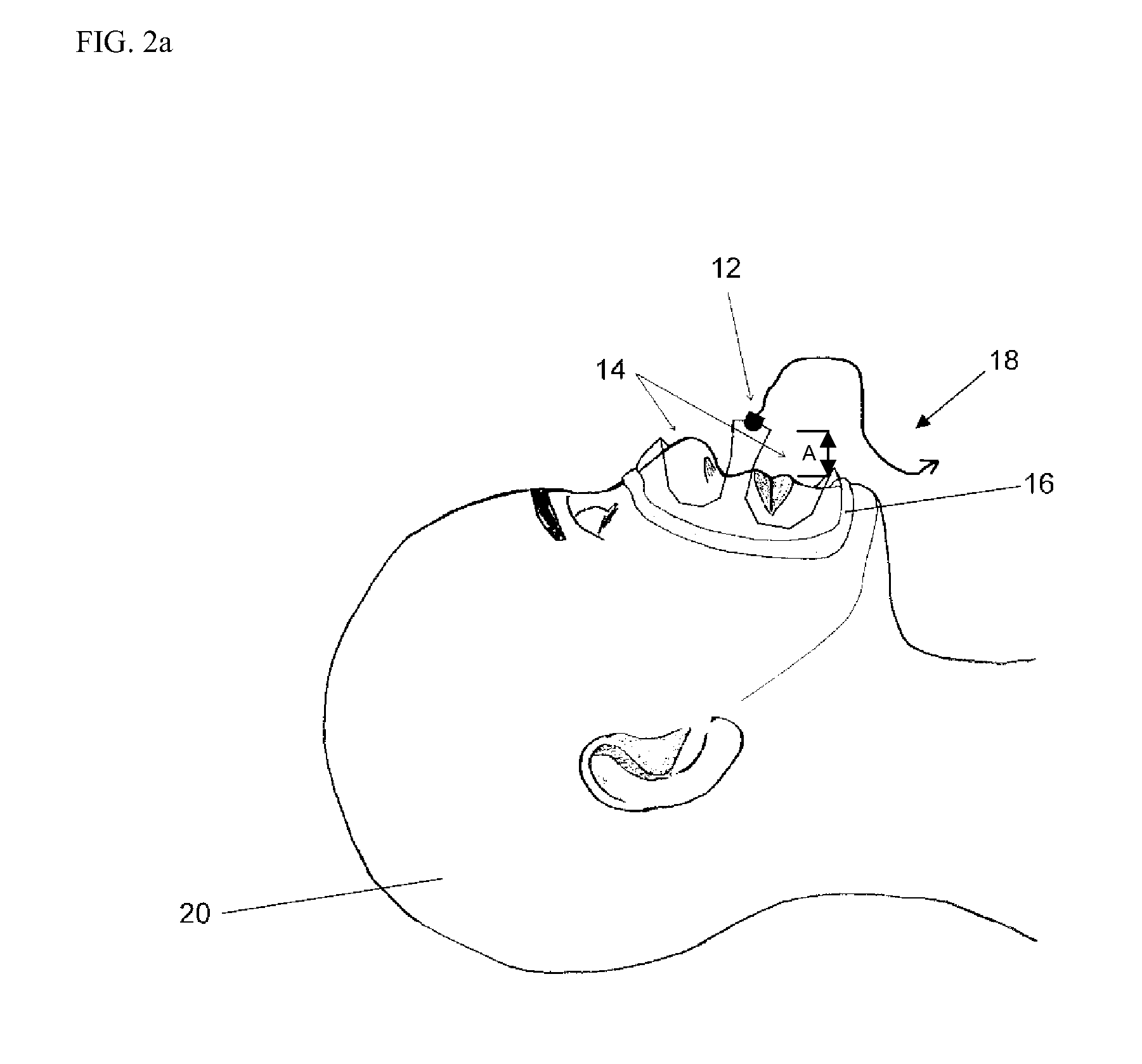
Disclosed herein is a mask to be worn by a subject on its face for use in respiratory monitoring and/or diagnostics. In general, the mask comprises at least one transducer responsive to sound and airflow for generating a data signal representative thereof, and a support structure shaped and configured to rest on the subject's face and thereby delineate a nose and mouth area thereof. The support structure comprises two or more outwardly projecting limbs that, upon positioning the mask, converge into a transducer supporting portion for supporting the at least one transducer at a distance from the area, thereby allowing for monitoring via the at least one transducer of both sound and airflow produced by the subject while breathing. The limbs may, in some examples, have along at least a portion thereof, an inward-facing channel defined therein for channeling toward a given transducer, air flow produced by the subject while breathing. A method is also disclosed for remotely diagnosing a breathing disorder of a subject.

Description

CROSS REFERENCE TO RELATED APPLICATIONS[0001]The present application is a continuation-in-part of copending international application no. PCT / CA2009 / 001644, filed Nov. 16, 2009, entitled “METHOD AND APPARATUS FOR MONITORING BREATHING CYCLE BY FREQUENCY ANALYSIS OF AN ACOUSTIC DATA STREAM”, which claims priority under 35 U.S.C. §119(e) to U.S. Provisional Patent Application No. 61 / 193,320, filed Nov. 17, 2008, entitled “TRACKING PHASES OF THE BREATHING CYCLE BY FREQUENCY ANALYSIS OF ACOUSTIC DATA.” The present application further claims priority under 35 U.S.C. §119(e) to U.S. Provisional Patent Application No. 61 / 272,460, filed Sep. 25, 2009, entitled “APPARATUS AND METHOD FOR USE IN THE DIAGNOSES OF OBSTRUCTIVE SLEEP BREATHING DISORDERS USING DIGITIZED ACOUSTIC DATA.” The disclosures set forth in the referenced applications are incorporated herein by reference in their entireties, including all information as originally submitted to the United States Patent and Trademark Office.FIE...

Claims


Application Information

Patent Timeline
Patent Type & Authority Applications(United States)
IPC IPC(8): A61B5/08
CPCA61B5/087A61B5/7257A61B5/097A61B5/6803A61B7/003A61M16/06A61M16/0633A61M2016/0027A61M2016/0033A61M2205/3375A61M2230/42
Inventor ALSHAER, HISHAMFERNIE, GEOFFREY ROYBRADLEY, T. DOUGLASLEVCHENKO, OLEKSANDR IGOROVICH
Owner UNIV HEALTH NETWORK
Why Eureka
Try Eureka