Liquid ejecting apparatus

a liquid ejecting and apparatus technology, applied in printing, other printing apparatus, etc., can solve problems such as image quality degradation

Active Publication Date: 2011-10-06
SEIKO EPSON CORP
View PDF2 Cites 3 Cited by
  • Summary
  • Abstract
  • Description
  • Claims
  • Application Information

AI Technical Summary

Benefits of technology

[0007]An advantage of some aspects of the invention is that a liquid ejecting apparatus is provided that includes a liquid ejection head including a pressure chamber in which a liquid is stored, a nozzle communicating with the pressure chamber and through which the liquid is ejected, and a pressure generator that applies pressure fluctuation to the liquid in the pressure chamber; and an ejection pulse generator that generates an ejection pulse that drives the pressure generator. The ejection pulse sequentially includes a first voltage change phase where a voltage is changed so as to expand the pressure chamber, a hold phase where an end edge potential of the first voltage change phase is maintained for a predetermined period, a second voltage change phase where the voltage is changed so as to contract the pressure chamber expanded in the first voltage change phase; and a time t1 between a start edge and the end edge of the first voltage change phase, and a time t2 between a start edge and an end edge of the second voltage change phase are specified in the following range:

Problems solved by technology

Such irregularity of the landing shape results in degradation in image quality, for example in the case where an image is recorded on recording paper by a printer.

Method used


Image

  • Liquid ejecting apparatus
  • Liquid ejecting apparatus
  • Liquid ejecting apparatus

Examples


first embodiment

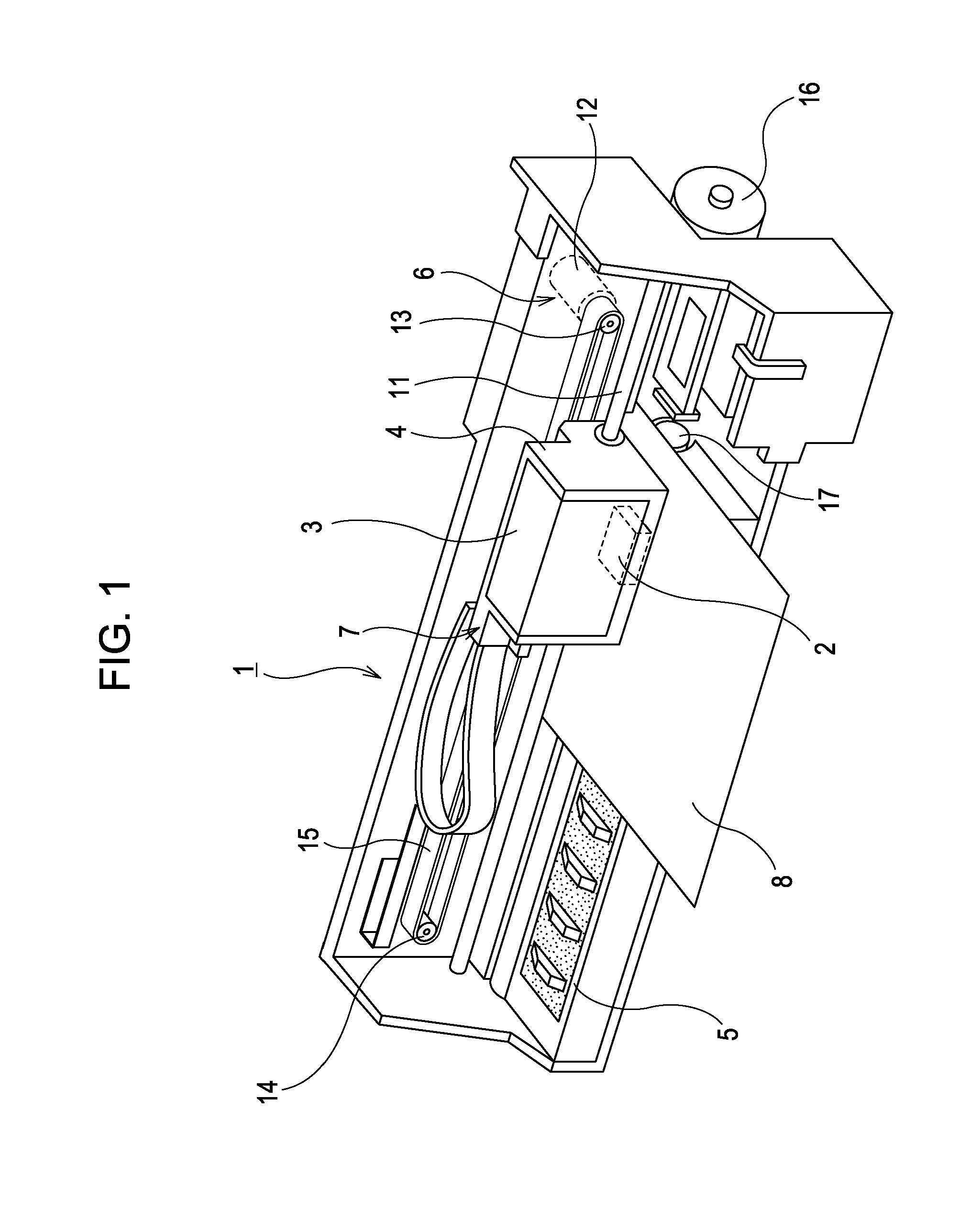
[0018]The printer 1 shown in FIG. 1 ejects an ink, an example of a liquid which may be used in association with the invention, onto a recording medium such as a recording paper sheet, a cloth, or a film. The recording medium is an example of the landing target on which the ejected liquid is to land. The printer 1 includes a carriage 4 on which a recording head 2 exemplifying the liquid ejection head is mounted, and an ink cartridge 3, an example of the liquid supply source, is removably mounted, a platen 5 disposed below the recording head 2, a carriage transport mechanism 6 that moves the carriage 4 in a direction of the width of a recording paper sheet 8 exemplifying the landing target, a linear encoder 7 that outputs an encoder pulse according to the movement of the carriage 4, and a paper feed mechanism 9 that transports the recording paper sheet 8 in a paper-feed direction.

[0019]The carriage transport mechanism 6 includes a guide shaft 11 disposed so as to extend in a main scan...

second embodiment

[0050]A second embodiment is similar to the first embodiment, unless otherwise stated specifically.

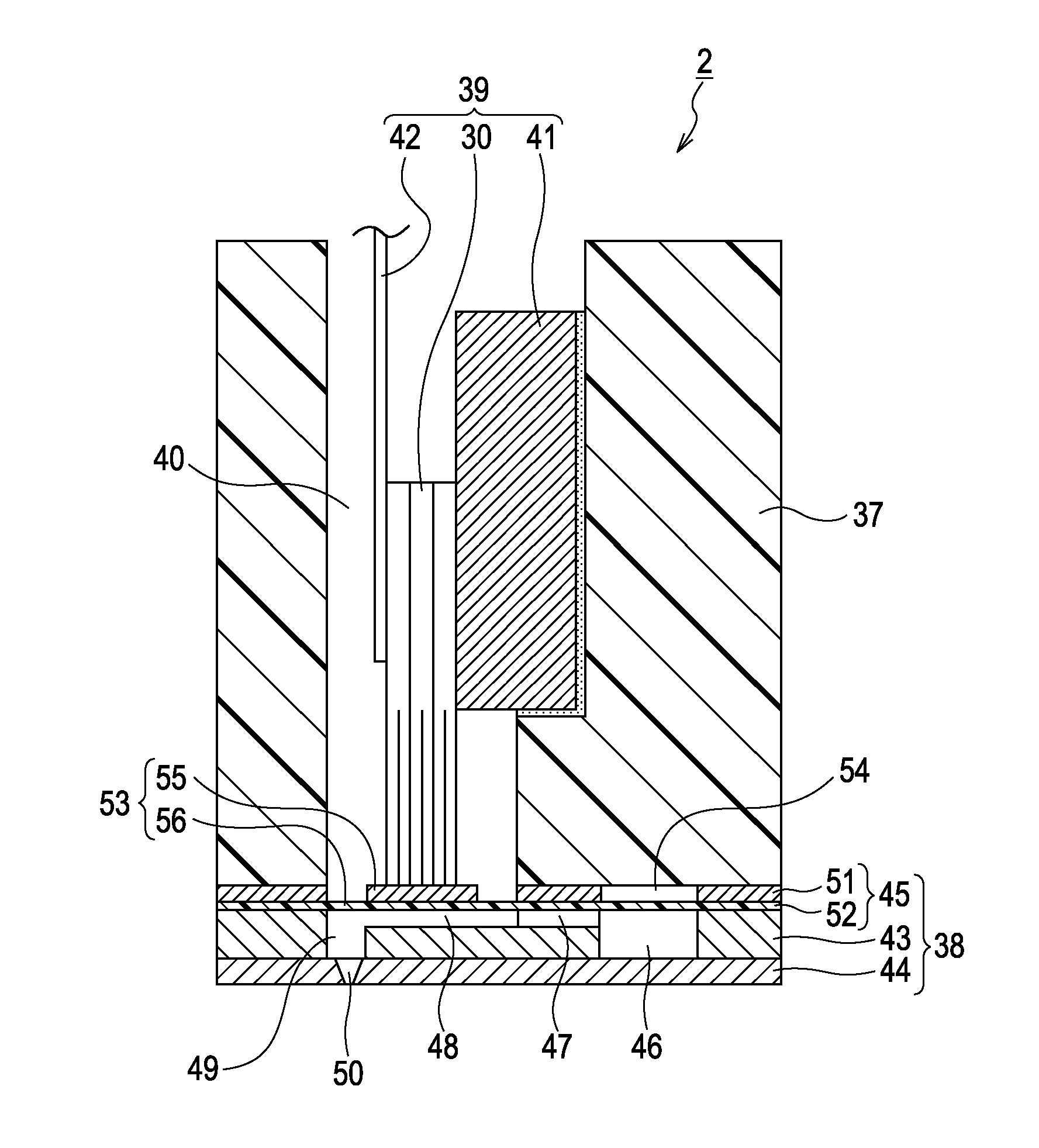
[0051]FIG. 7 is a wave diagram showing a configuration of an ejection pulse DP′ according to the second embodiment. The ejection pulse DP′ according to the second embodiment includes the expansion phase p1 where the potential is increased from the reference potential VB corresponding to the contracted volume of the pressure chamber 48 to the expansion potential VH, so that the pressure chamber 48 expands from the contracted volume to the expanded volume, the expansion hold phase p2 where the expansion potential VH is maintained for holding the expanded state of the pressure chamber 48 for a predetermined period, and the contraction phase p3 where the potential is decreased from the expansion potential VH to the reference potential VB, so that the pressure chamber 48 contracts to the contracted volume. The ejection pulse DP′ is different from the ejection pulse DP according to the first...


PUM


Abstract

An ejection pulse DP sequentially and continuously includes an expansion phase p1 where a voltage changes so as to cause a pressure chamber to expand, an expansion hold phase p2 where a potential at an end edge of the expansion phase is maintained for a predetermined time, a contraction phase where the voltage changes so as to cause the pressure chamber to contract, and a time t1 between a start edge and the end edge of the expansion phase and a time t2 between a start edge and an end edge of the contraction phase are specified in the following range, respectively:
Tc/3≦t1≦Tc   (A)
Tc/3≦t2≦Tc   (B)

Description

BACKGROUND OF THE INVENTION[0001]The entire disclosure of Japanese Patent Application No. 2010-77521, filed Mar. 30, 2010 is expressly incorporated herein by reference.[0002]1. Technical Field[0003]The present invention relates to a liquid ejecting apparatus that drives a pressure generator with an ejection pulse to thereby eject a liquid through a nozzle.[0004]2. Related Art[0005]A liquid ejecting apparatus currently known in the art drives a pressure generator such as a piezoelectric vibrator or a heating phase by applying an ejection drive pulse to the piezoelectric vibrator or heating phase. The ejection drive pulse causes the piezoelectric vibrator or heating phase to create pressure fluctuation of a liquid in a pressure chamber, which in turn causes the liquid to be ejected through a nozzle communicating with the pressure chamber. For example, in a printer disclosed in Japanese Patent No. 3412682, a drive pulse (drive waveform) is employed that includes a preparatory expansion...

Claims


Application Information

Patent Timeline
Patent Type & Authority Applications(United States)
IPC IPC(8): B41J29/38
CPCB41J2/04588B41J2/04581
Inventor ZHANG, JUNHUA
Owner SEIKO EPSON CORP
Why Eureka
Try Eureka