
Reciprocating compressors having timing valves and related methods

a compressor and timing valve technology, applied in the direction of pump components, pump control, pump parts, etc., can solve the problems of large actuator, short actuation time, inefficiency of reciprocating compressor, etc., and achieve the effect of reducing the effect of clearance volume and increasing suction volum

Active Publication Date: 2014-12-25
NUOVO PIGNONE TECH SRL
View PDF21 Cites 3 Cited by
  • Summary
  • Abstract
  • Description
  • Claims
  • Application Information

AI Technical Summary

Benefits of technology

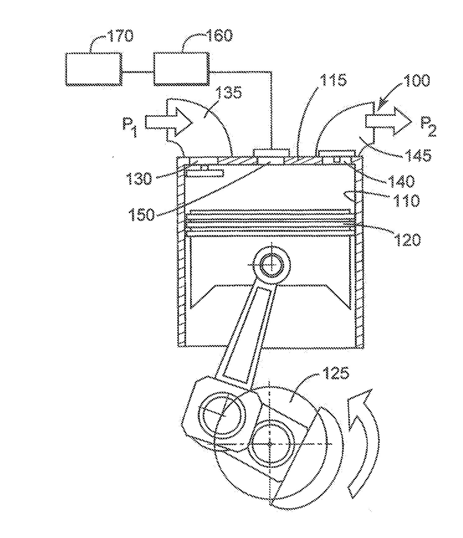
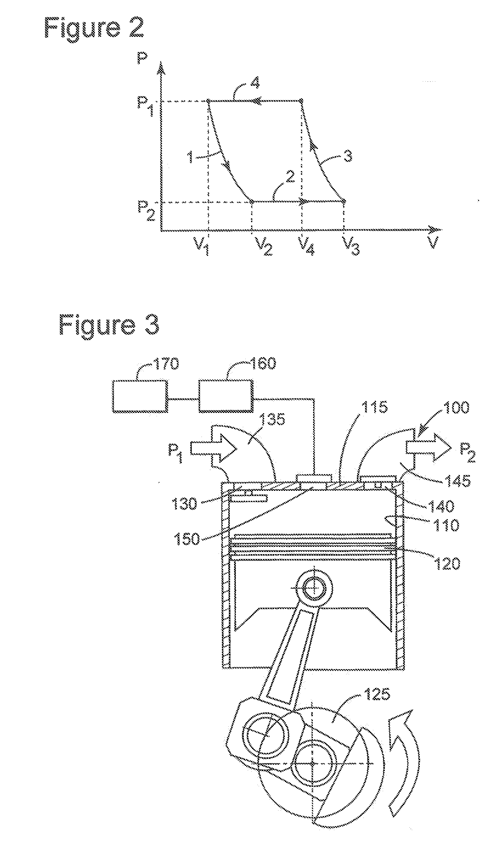
The patent describes a timing valve that is used in a compressor to improve its efficiency. The timing valve opened during the expansion phase of the compressor increases the suction volume and reduces the effect of clearance volume. This results in a higher volumetric efficiency of the compressor. The method includes controlling the timing valve to open during the expansion phase of the compression cycle. The timing valve has a smaller flow area than the suction valve of the compressor. Overall, the invention provides a way to increase the performance of reciprocating compressors in oil and gas industry.

Problems solved by technology

Compressors used in oil and gas industry, have to meet industry specific requirements that take into consideration, for example, that the compressed fluid is frequently corrosive and combustible.
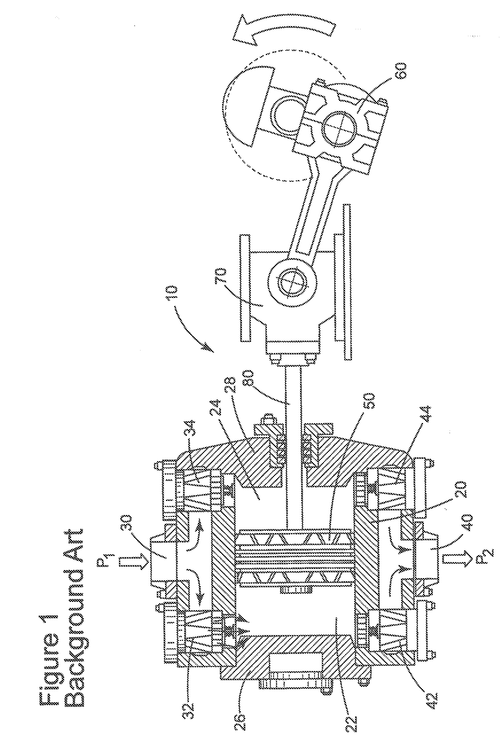
One important source of inefficiency in the reciprocating compressor is due to the clearance volume, which is a volume of compressed gas which is not delivered from the chamber during to the delivery phase.
Such a large force would require a large actuator which would also have a short actuation time.
At a practical level, opening the suction valve early is not currently feasible.

Method used


Image

  • Reciprocating compressors having timing valves and related methods
  • Reciprocating compressors having timing valves and related methods
  • Reciprocating compressors having timing valves and related methods

Examples


Embodiment Construction

[0028]The following description of the exemplary embodiments refers to the accompanying drawings. The same reference numbers in different drawings identify the same or similar elements. The following detailed description does not limit the invention. Instead, the scope of the invention is defined by the appended claims. The following embodiments are discussed, for simplicity, with regard to the terminology and structure of reciprocating compressors used in oil and gas industry. However, the embodiments to be discussed next are not limited to this equipment, but may be applied to other equipment.

[0029]Reference throughout the specification to “one embodiment” or “an embodiment” means that a particular feature, structure, or characteristic described in connection with an embodiment is included in at least one embodiment of the subject matter disclosed. Thus, the appearance of the phrases “in one embodiment” or “in an embodiment” in various places throughout the specification is not ne...


PUM


Abstract

A reciprocating compressor for the oil and gas industry, the reciprocating compressor has a chamber, a timing valve, an actuator and a controller. A fluid entering the chamber via a suction valve is compressed inside the chamber, and evacuated from the chamber via a discharge valve. The timing valve is located between the chamber and a fluid volume at a relief pressure that is lower than a pressure in the chamber when the timing valve is opened. The actuator is configured to actuate the timing valve. The controller is configured to control the actuator such that to open the timing valve during an expansion phase of the compression cycle, and to close the timing valve when the relief pressure becomes equal to the pressure in the chamber or when the suction valve is opened.

Description

BACKGROUND[0001]1. Technical Field[0002]Embodiments of the subject matter disclosed herein generally relate to reciprocating compressors used in oil and gas industry, and, more particularly, to increasing a suction volume and mitigating the effect of the clearance volume by using a timing valve that is actuated to open during the expansion phase of the compression cycle.[0003]2. Discussion of the Background[0004]Compressors used in oil and gas industry, have to meet industry specific requirements that take into consideration, for example, that the compressed fluid is frequently corrosive and combustible. American Petroleum Institute (API), the organization setting the recognized industry standard for equipment used in oil and gas industry has issued a document, API618, listing a complete set of minimum requirements for reciprocating compressors.[0005]The compressors may be classified as positive displacement compressors (e.g., reciprocating, screw, or vane compressors) or dynamic co...

Claims


Application Information

Patent Timeline
Patent Type & Authority Applications(United States)
IPC IPC(8): F04B49/03F04B35/01
CPCF04B35/01F04B49/03F04B7/00F04B39/10F04B49/16F04B49/22F04B49/225
Inventor BAGAGLI, RICCARDOTOGNARELLI, LEONARDO
Owner NUOVO PIGNONE TECH SRL
Learn More