Internal combustion engine with emission treatment interposed between two expansion phases

a technology of emission treatment and combustion engine, which is applied in the direction of engine components, machines/engines, mechanical equipment, etc., to achieve the effect of reducing emissions

Active Publication Date: 2013-12-17
GM GLOBAL TECH OPERATIONS LLC
View PDF53 Cites 3 Cited by
  • Summary
  • Abstract
  • Description
  • Claims
  • Application Information

AI Technical Summary

Problems solved by technology

Therefore, current engine designs face a tradeoff between optimizing the work extraction from the working gases and leaving enough energy in the form of heat to allow catalytic converters to effectively clean the discharged working gases.
Thus, present internal combustion engine designs, for example Diesel, Otto, Rotary, or Atkinson cycle engines when used in an automotive vehicle compromise between maximum practical expansion during the power stroke and leaving enough heat in the output gases to provide for effective catalytic after-treatment.

Method used


Image

  • Internal combustion engine with emission treatment interposed between two expansion phases
  • Internal combustion engine with emission treatment interposed between two expansion phases
  • Internal combustion engine with emission treatment interposed between two expansion phases

Examples


Embodiment Construction

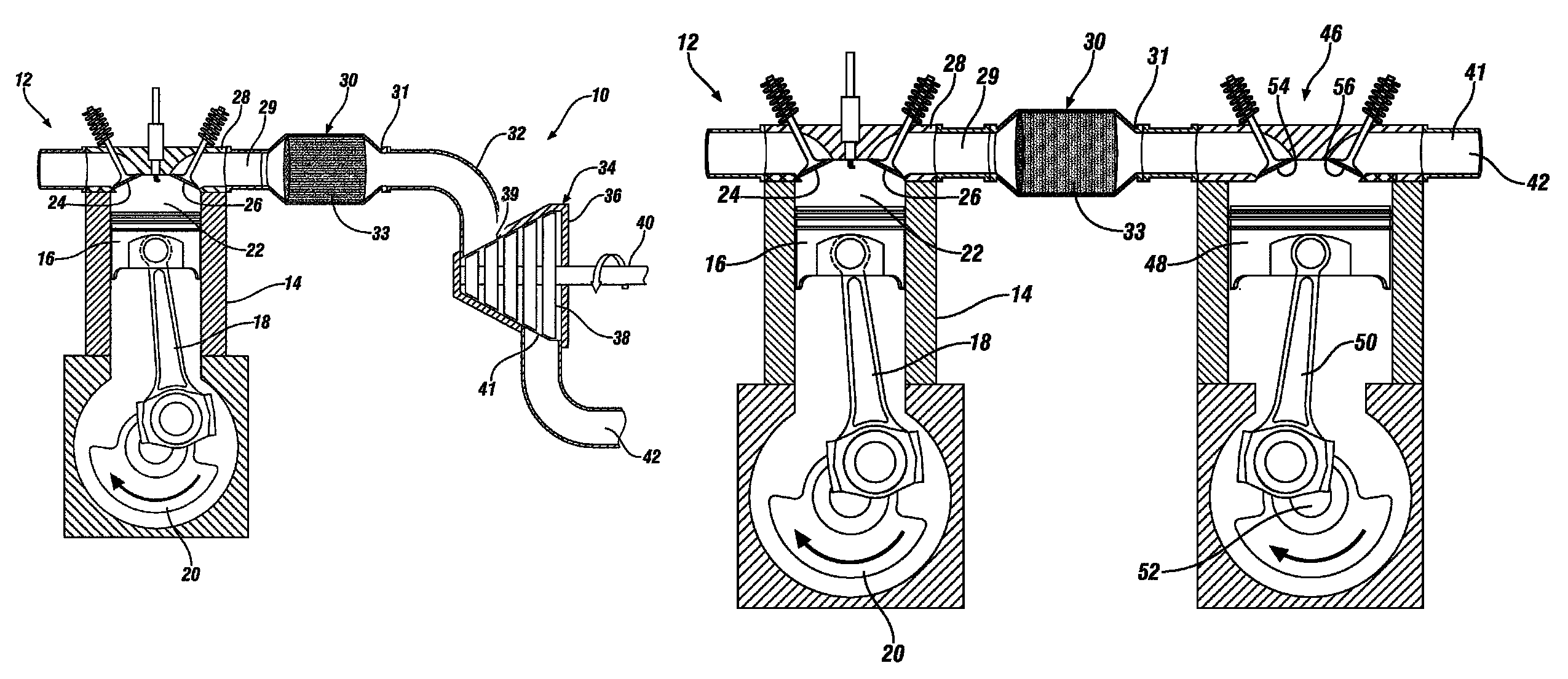
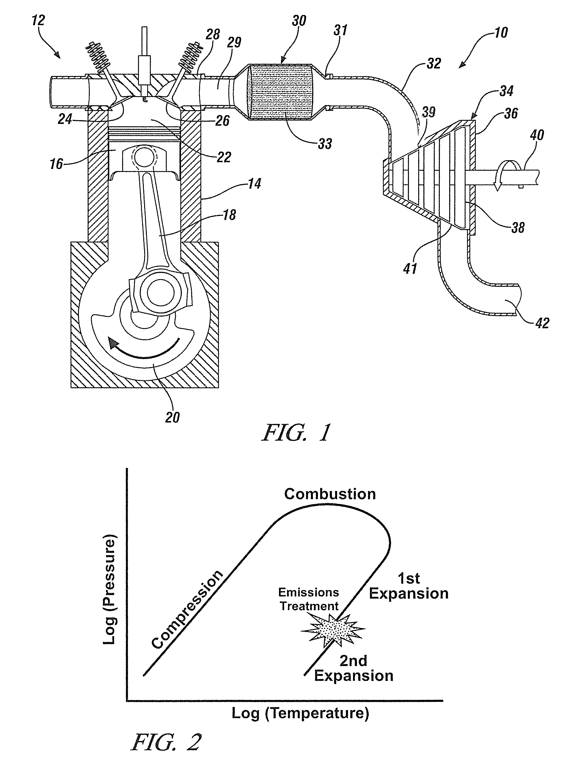
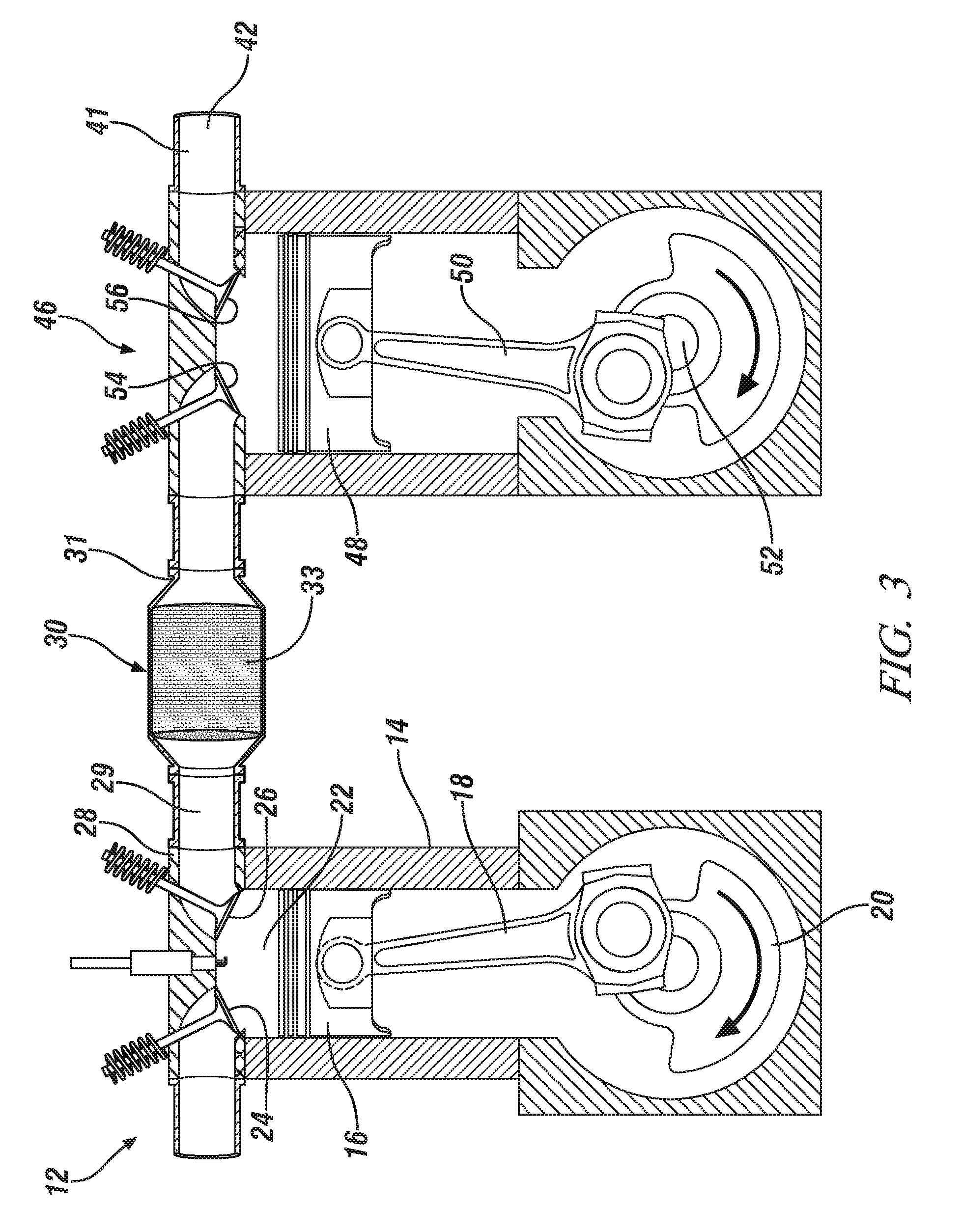
[0015]Referring now to FIG. 1, an engine 10 has a piston engine section 12. The engine section 12 can look conventional with an engine block 14, piston 16, crank arm 18, crankshaft 20 and working chamber 22 often referred to as a cylinder. Inlet and outlet valves 24 and 26 also commonly referred to as intake value 24 and exhaust value 26 allow for intake of air and exhaust or discharge of the working gases, also referred to as the combustion gases. The engine section 12 operates and functions like a conventional engine during the induction, compression and combustion phase. However, the power stroke or expansion phase is reduced compared to a conventional engine. As such, the working gases remain at higher pressures at the time when the outlet valves open and the discharge stroke commences.

[0016]While a piston engine is shown in FIG. 1 as the first expander, it should be understood other engines may be used. Diesel, Otto cycle, Atkinson, Miller cycle, Brayton cycle, or split-cycle e...


PUM


Abstract

An internal combustion engine has a first work extraction station for extracting work from combustion and expansion of working gases. An emission treatment station treats the working gases after leaving the first extraction work station for reducing emissions. A second work extraction station receives the working gases from the emission treatment station for a second extraction of work from the working gases.

Description

TECHNICAL FIELD[0001]This disclosure pertains to an internal combustion engine system that provides treatment of combustion gases between first and second expansion phases of the gases.BACKGROUND OF THE INVENTION[0002]Internal combustion engines have a power stroke defined by combustion and expansion of working gases. In motor vehicles, it is required in many geographic regions to treat the discharged working gases for reducing emissions, particularly HC, CO and NOx and particulate emissions.[0003]Present emission reducing technology requires that the discharged working gases need to be at a certain minimum temperature in order for the catalytic after-treatment process to be effective. If conventional engines were adjusted, i.e. by varying compression ratios, fuel ratios and valve timing to run most efficiently, the discharged exhaust gases would be cooler than the required minimum temperature. Therefore, current engine designs face a tradeoff between optimizing the work extraction ...

Claims


Application Information

Patent Timeline
Patent Type & Authority Patents(United States)
IPC IPC(8): F02G3/00F02B41/06F02B25/00F02B33/22
CPCF02B41/08F01N3/10F01N13/00F01N2340/06
Inventor DURRETT, RUSSELL P.GOPALAKRISHNAN, VENKATESHNAJT, PAUL M.
Owner GM GLOBAL TECH OPERATIONS LLC
Why Eureka
Try Eureka