Suspension method and shock-absorbing device for an automobile

A damping device and damping technology, applied in suspension, elastic suspension, vehicle components, etc., can solve the problems of weakened trim control, imperfect stiffness and damping, and difficulty in maintaining mechanical quality, and achieve the effect of favorable action and cost reduction.

Inactive Publication Date: 2014-05-07
MAURO BIANCHI
View PDF10 Cites 3 Cited by
  • Summary
  • Abstract
  • Description
  • Claims
  • Application Information

AI Technical Summary

Problems solved by technology

However, this damping accessory has some disadvantages
[0005] The first disadvantage is that this fitting has an overall dimension that requires it to be extended to accommodate the reset fitting, which guarantees two different degrees of stiffness for the compression and expansion phases
[0006] The second disadvantage is the need to insert elastic elements inside the damping fittings, which leads to non-negligible reliability problems, inside the fittings, elastic parts in very hot environments and in the presence of hydraulic press fluids (fluids can be corrosive) Difficulty maintaining its mechanical quality
[0007] A third disadvantage is that accessories with two stiffness levels that are installed on mass-produced vehicles that face widely varying loads face the problem of impairm...

Method used


Image

  • Suspension method and shock-absorbing device for an automobile
  • Suspension method and shock-absorbing device for an automobile
  • Suspension method and shock-absorbing device for an automobile

Examples


Embodiment Construction

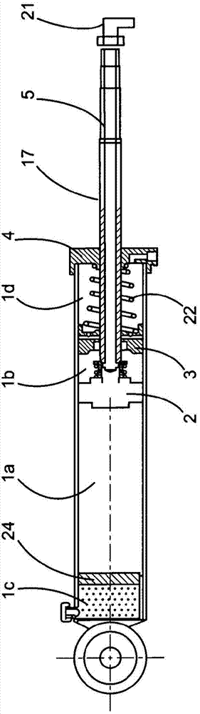
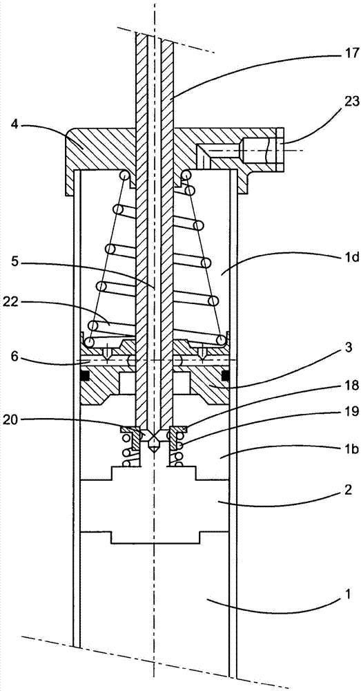
[0079] figure 1 The damping fitting 1 is shown. The damping fitting 1 is shown as an oleo-pneumatic damping device, but the invention is not limited to this damping device and can be applied to any type of damping device. The damping fitting 1 has a piston 2 which is movable inside the damping fitting 1 by dividing the interior into two chambers 1a and 1b.

[0080] The piston 2 is connected to a connecting rod 17 which extends lengthwise to and inside the damping fitting 1 and exits said interior through the longitudinal end of the fitting 1 . The longitudinal ends form the upper closure 4 of the damping fitting 1 . At the other longitudinal end of the damping fitting 1 a gas (for example nitrogen) inlet is provided to control the movable layer which puts the oil contained in the damping fitting under pressure.

[0081] For oil-pneumatic damping fittings, to ensure continuous movement of the piston 2 and connecting rod 7 fittings, the piston 2 is immersed in hydraulic fluid...


PUM


Abstract

The present invention relates to a suspension method and to a shock-absorbing device for an automobile in the broadest sense of the term, i.e. any vehicle having a suspension and moving under its own power. Said shock-absorbing device includes a damping assembly (1) having, on the inside thereof, a piston (2) connected to a rod (17), the piston (2) and the rod (17) combined therewith being movable, in both the compression and expansion direction, about a static position inside the damping assembly (1) in order to provide a shock-absorbing function, the inside of the damping assembly (1) being filled with a hydraulic fluid, characterized in that said assembly (1) engages with a means for varying the damping effect so as to produce: a compression phase consisting of a compression sub-phase, directed from the static position toward the maximum compression position of the piston (2), and of an expansion sub-phase, directed from said maximum compression position toward the static position, respectively, and an expansion phase consisting of an expansion sub-phase, directed from the static position toward the position of maximum expansion of the piston (2), and of an expansion sub-phase, directed from said maximum position toward the static position, respectively, the means for varying the damping effect controlling the damping assembly such that the damping value of the compression sub-phase of the compression phase and/or the expansion sub-phase of the expansion phase is different from the damping value of the expansion sub-phase of the compression phase and the compression sub-phase of the expansion phase, respectively. According to the invention, provided is a step of modifying the damping value with separate values for the compression direction as well as for the expansion direction for each of the work sectors of the shock absorber depending on whether the work is being carried out between the static position of the suspension and the fully compressed position, or between the static position of the suspension and the fully expanded position.

Description

technical field [0001] The present invention relates to a method of suspension and a damping device with damping accessories for any type of motor vehicle (including quadricycles (Q-cycles), racing cars, sports cars, motorcycles, ATVs, trucks and / or trailers) . Background technique [0002] The applicant of this patent application has filed several patent applications based on the so-called contractility concept, which relate to damping fittings with two different stiffness levels in order to have a compression phase and an expansion phase The resting position of the vehicle is the center. This is described in particular in document WO-A-91 / 04876, which shows a damping fitting in which the stiffness during the expansion stroke is significantly higher than the stiffness of said fitting during the compression stroke, And the ratio is about 1:3. [0003] Document FR-A-2664210 discloses an improvement of this damping fitting by providing a flexible connection inserted between...

Claims


Application Information

Patent Timeline
IPC IPC(8): F16F9/49F16F9/516F16F9/06
CPCF16F9/065F16F9/49F16F9/516B60G13/06B60G17/08F16F9/22
Inventor 毛罗·比安基
Owner MAURO BIANCHI
Why Eureka
Try Eureka