Method and device for converting thermal energy into kinetic energy

a technology of thermal energy and kinetic energy, which is applied in the direction of closed-cycle machines/engines, hot gas positive displacement engine plants, etc., can solve the problems of low overall efficiency, energy loss, and not very suitable for light or cold refrigerators

Inactive Publication Date: 2005-08-11
DONAUWIND ERNEUERBARE ENERGIEGEWINNUNG & BETEILIGUNGS
View PDF15 Cites 3 Cited by
  • Summary
  • Abstract
  • Description
  • Claims
  • Application Information

AI Technical Summary

Benefits of technology

[0036] The aim of the invention is to create a method of the type set out above, that on the one hand, avoids the above disadvantages and, on the other hand, makes it possible for the first time to embody a Stirling motor in such a way that its mode of action can be approximated to the ideal Stirling process much better than before. This aim is fulfilled by the invention.

Problems solved by technology

The energy contained in wood is very useful for heating purposes, for example, but is not very suitable for the generation of light or cold for the refrigerator, etc.
Each of these energy conversions has a specific degree of efficiency, i.e., energy is lost every time and the overall efficiency is accordingly low.
In other conversion processes, such as e.g., the conversion of chemical energy in petroleum into kinetic energy to drive cars, ships, trains or even aircraft, the efficiency is no better either, although the conversion chain in these processes is shorter.
If you only look at the huge amounts of electricity consumed worldwide, for instance, you can see what enormous quantities of energy cannot be used and are lost.
The loss of primary energy not usable for conversion into electric energy is already a major problem, especially because of the waste of limited resources, but the environmental pollution inseparably associated with the conversion of chemical energy into thermal energy through combustion is a much more serious problem for future generations, such as climate changes due to greenhouse gases, as shown by the CO2 problem, for example.
And although the Stirling motor has a significantly higher efficiency that the steam engine and the carburetor or diesel engine on principle, it has still not become very widespread.
In practice, however, exact implementation, i.e., an exact copy of the ideal, or rather the theoretical, process is not possible.
In embodied machines, a number of design-related deviations have to be accepted that have a negative effect on efficiency and performance.
In the Stirling motors designed or built to date, for instance, it has not been possible to realize either isochoric heat absorption or isochoric heat dissipation, nor isothermal compression or isothermal expansion.
The big disadvantage of α motors is the piston packing in the hot expansion chamber, which greatly limits the lifetime of the motor and for which a satisfactory solution has not been found to date.
Another disadvantage is the crank drive with the associated major deviation from the theoretical process and the low degree of efficiency.
So far, a number of different cylinder arrangements have been developed, such as parallel, aligned opposite, parallel opposite, V cylinders or the Finkelstein rotation cylinder, etc., which all function in the same way, have the same weaknesses, and the same low degree of efficiency.
The major disadvantage of β machines, similar to the α machines, is seals running dry.
Another major disadvantage of the β machines is the complex sealing system of the displacer slide rod in the compression piston.
In return, the dead volume detrimental to efficiency is increased.
The greatest disadvantages of γ machines, as already described for α and β machines, are the dry seals of the working piston.
Moreover, the motion of piston and displacer caused by the crankshaft drive or crank-like drive, which makes a good approximation to the ideal Stirling process impossible in the embodied machines.
Therefore, the γ machine also has a significantly poorer efficiency than the ideal Stirling process.
Another major disadvantage of γ machines is the greater dead volume, which has an additional negative impact on efficiency, and the relatively low compression ratio that can be achieved, so that only modest volume performance is possible.
The efficiency of double-action ax machines such as the Franchot Stirling motor is not better than that of single-action α machines.
Although the arrangement of heater, regenerator and cooler in the Siemens Stirling motor was chosen in such a way that the piston sealing in the casing is located in the cold section, the basic disadvantages of the α machines remain.
None of these embodiments has resulted in an improvement of efficiency; on the contrary, in addition to poorer efficiency compared with the α machines, the disadvantages and problems were only enhanced.
All these various embodiments of Stirling motors have the additional disadvantages due to the clearance volumes in heat exchangers, regenerators and return-flow pipes in common, which additionally lower the pressure ratio and thus the efficiency.

Method used


Image

  • Method and device for converting thermal energy into kinetic energy
  • Method and device for converting thermal energy into kinetic energy
  • Method and device for converting thermal energy into kinetic energy

Examples


Embodiment Construction

[0087] By way of introduction, it is noted that in the described embodiment the same parts and the same states are allocated the same reference numbers and the same component names, whereby the disclosures contained throughout the description can be applied by analogy to the same parts and the same states with the same reference numbers or same component names.

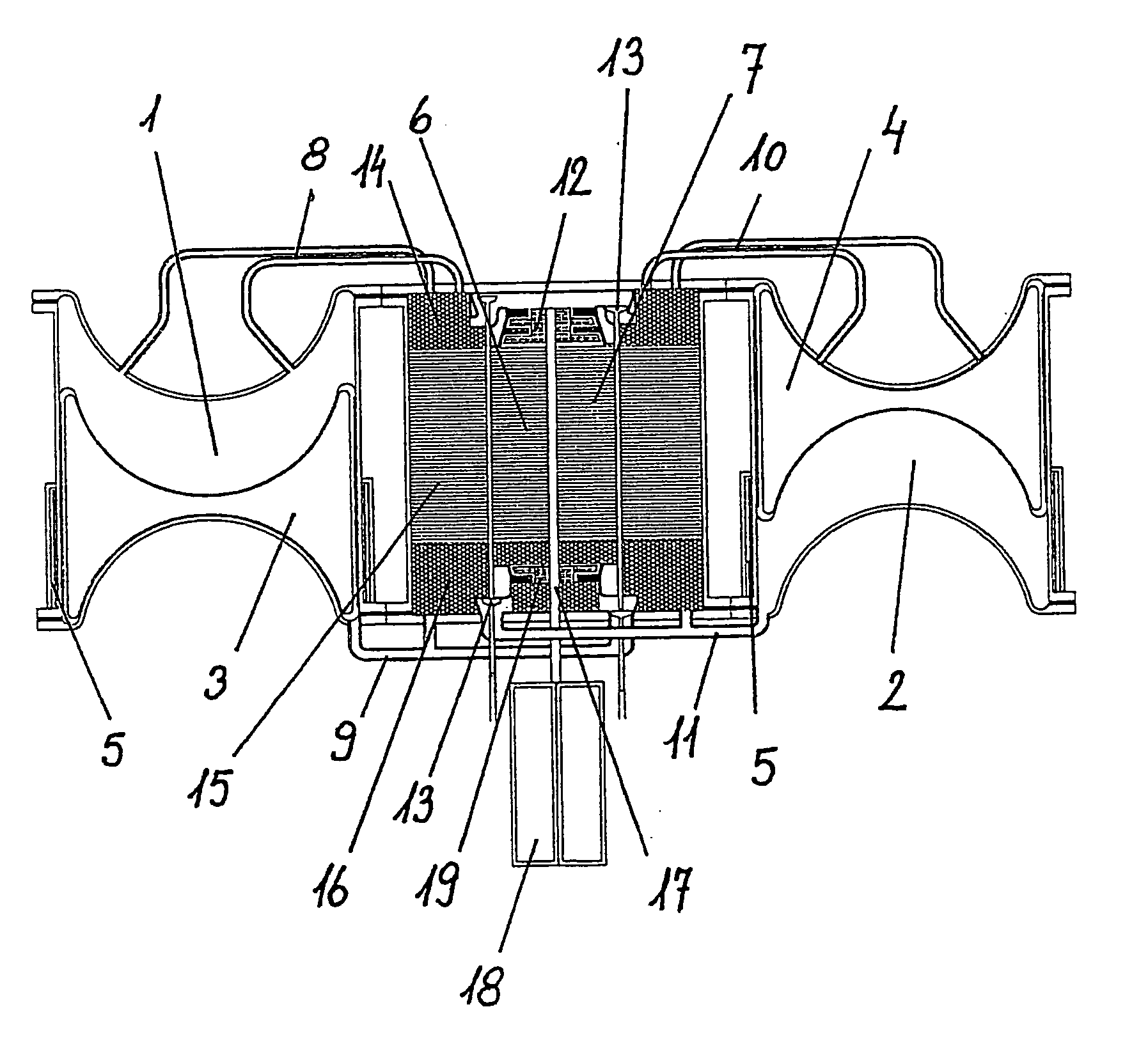
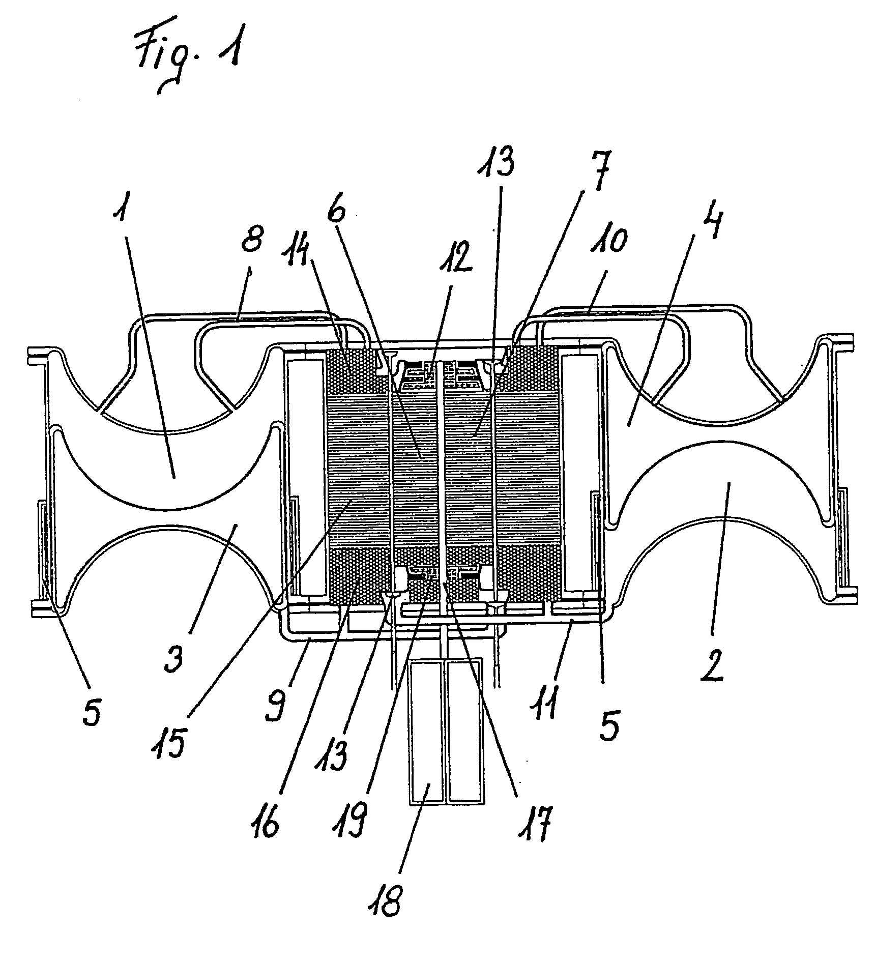
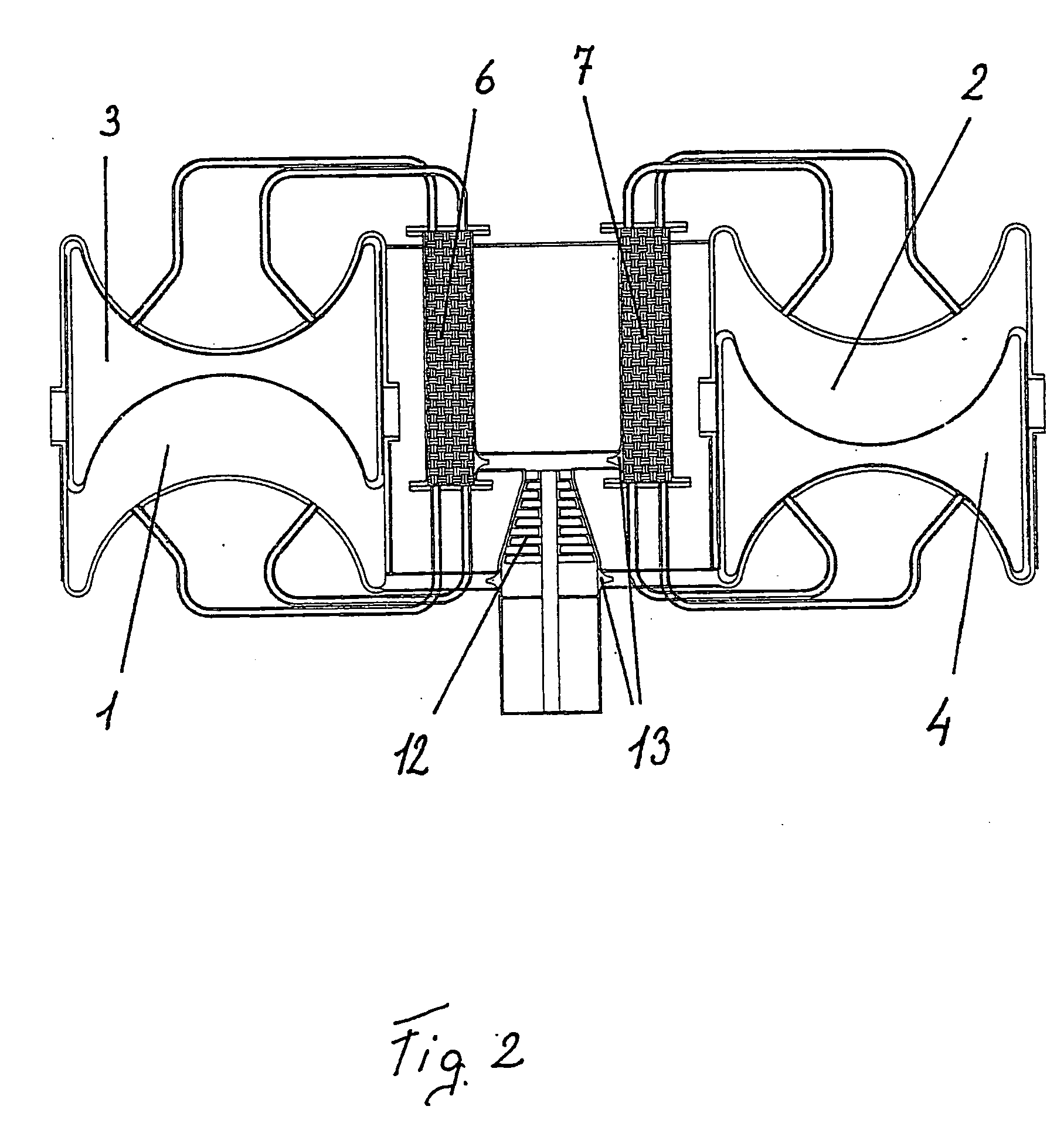
[0088]FIG. 1 shows a device using a medium for conversion of thermal energy into kinetic energy which has two enclosed chambers 1, 2. Each chamber 1, 2 is divided by a movable displacer 3, 4 into two sections, namely an expansion chamber and a compression chamber. Each displacer 3, 4 can be moved by a drive 5, which can be, in particular, a linear drive. Each chamber 1, 2 has a regenerator 6, 7 allocated to it. Both sections of the chambers 1, 2 are connected to regenerators 6, 7 via pipes 8, 9 and 10, 11.

[0089] One section, i.e., the expansion chamber, of each chamber 1, 2 is connected to a work machine 12. The expansion ch...


PUM


Abstract

Method and device for converting, thermal energy into kinetic energy . The device includes at least two enclosed chambers. Each enclosed chamber has an expansion chamber, a compression chamber, and a displacer. The device also includes at least one drive to move the displacers, at least one regenerator, and control units are also used. A machine is arranged between the at least two enclosed chambers. The method includes a compression phase where a medium is compressed with one displacer, a heat absorption phase where heat is absorbed in the at least one regenerator, an expansion phase where heat is supplied in an expansion chamber and guided through the machine to release effective work, and a heat dissipation phase where heat is dissipated in the at least one regenerator and returned to the compression chamber. The medium flows back and forth between the at least two enclosed chambers. Heat absorption phase occurs before the machine and heat dissipation phase occurs after the machine. This Abstract is not intended to define the invention disclosed in the specification, nor intended to limit the scope of the invention in any way.

Description

CROSS-REFERENCE TO RELATED APPLICATIONS [0001] The instant application is a continuation of International Application No. PCT / AT03 / 00160 filed on Jun. 2, 2003 and published as International Publication WO 03 / 102403 on Dec. 11, 2003, the disclosure of which is hereby expressly incorporated by reference hereto in its entirety. The instant application also claims priority under 35 U.S.C. § 119 of Austrian Application Nos. A 843 / 02, filed on Jun. 3, 2002 and A 767 / 03, filed on May 19, 2003. BACKGROUND OF THE INVENTION [0002] 1. Field of the Invention [0003] The invention relates to a method for converting thermal energy into kinetic energy, whereby a medium undergoes the following changes of state in at least one chamber separated by a displacer: compression, preferably isothermal compression, with thermal dissipation in a compression chamber; heat absorption, preferably isochoric heat absorption, in a regenerator during passage of the medium from a compression chamber to an expansion c...

Claims


Application Information

Patent Timeline
Patent Type & Authority Applications(United States)
IPC IPC(8): F01B29/10F02G1/04F02G1/044
CPCF02G1/044
Inventor HOLECEK, CAMILLOENGELHART, KLAUS
Owner DONAUWIND ERNEUERBARE ENERGIEGEWINNUNG & BETEILIGUNGS
Why Eureka
Try Eureka