Apparatus and method for remote control between mobile communication terminals

a mobile terminal and remote control technology, applied in electrical equipment, two-way working systems, television systems, etc., can solve the problems of inability to use video call-based remote control schemes, inability to control mobile terminals with different user interfaces, and difficulty for old or blind people to control mobile terminals

Active Publication Date: 2011-10-06
SAMSUNG ELECTRONICS CO LTD
View PDF5 Cites 11 Cited by
  • Summary
  • Abstract
  • Description
  • Claims
  • Application Information

AI Technical Summary

Benefits of technology

The present invention aims to provide an apparatus and method for remote control between mobile terminals. The technical effects of this invention include solving problems and disadvantages associated with current remote control methods, providing improved efficiency, and enhancing user experience.

Problems solved by technology

The technical problem addressed in this patent is the difficulty for old or blind users to control additional functions of mobile terminals, such as video calls, and the lack of a video call-based remote control scheme that can be used with different user interfaces and mobile terminals.

Method used


Image

  • Apparatus and method for remote control between mobile communication terminals
  • Apparatus and method for remote control between mobile communication terminals
  • Apparatus and method for remote control between mobile communication terminals

Examples


Embodiment Construction

[0025]FIGS. 1 through 5, discussed below, and the various embodiments used to describe the principles of the present disclosure in this patent document are by way of illustration only and should not be construed in any way to limit the scope of the disclosure. Those skilled in the art will understand that the principles of the present disclosure may be implemented in any suitably arranged communication device. Preferred embodiments of the present invention will be described below, with reference to the accompanying drawings. In the following description, detailed descriptions of well-known functions or configurations will be omitted as they would unnecessarily obscure the subject matters of the present invention.

[0026]The present invention provides an apparatus and method for remote control between mobile terminals.

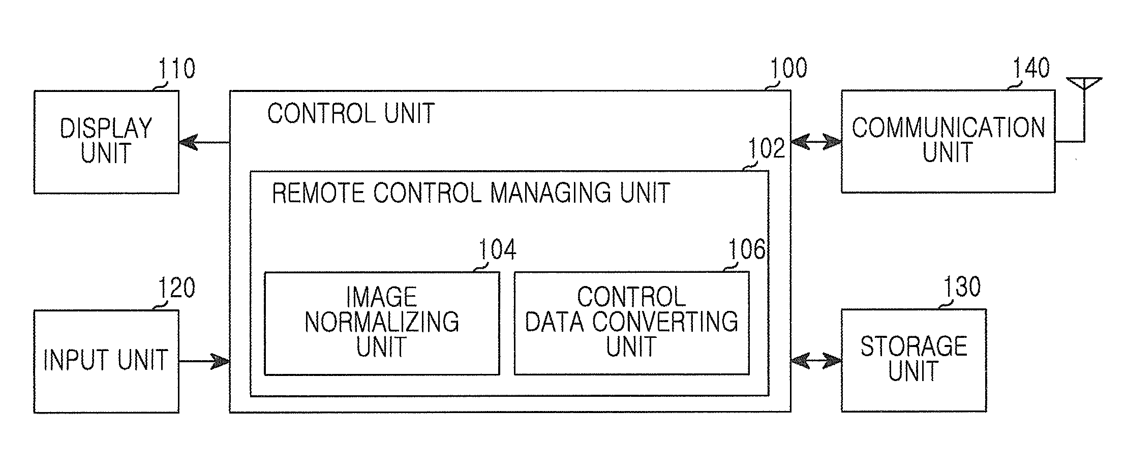
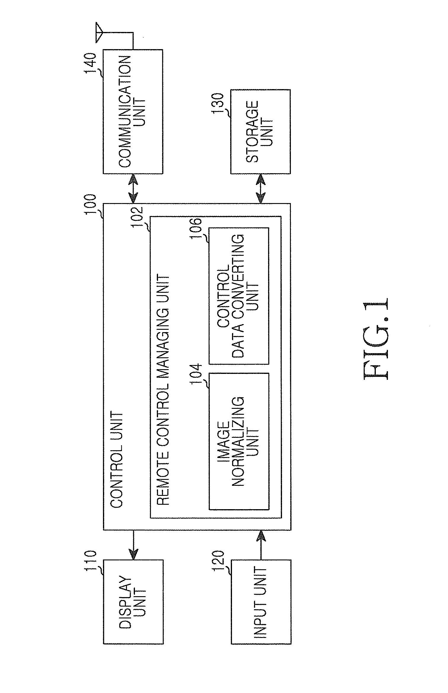
[0027]FIG. 1 is a block diagram of a mobile terminal according to an embodiment of the present invention.

[0028]Referring to FIG. 1, the mobile terminal includes a control...


PUM


Abstract

An apparatus and method in a mobile terminal support remote control with other mobile terminals. A video call is connected between the mobile terminal with a corresponding terminal. A remote control request message is transmitted through a control channel to the corresponding terminal. A remote control acceptance message is received through the control channel from the corresponding terminal. And a control message including control data that corresponds to a user input is transmitted through the control channel to the corresponding terminal.

Description


Claims


Application Information

Patent Timeline
Owner SAMSUNG ELECTRONICS CO LTD
Why Eureka
Try Eureka