Pneumatic mattress

Inactive Publication Date: 2011-10-13
LINET SPOL
View PDF36 Cites 11 Cited by
  • Summary
  • Abstract
  • Description
  • Claims
  • Application Information

AI Technical Summary

Benefits of technology

Conveniently, the groups of cells in the top layer are connected at a knee position, that is to say a nominal position in the mattress at which a user's knee can be expected to be. This arrangement allows the mattress to flex when supported on a bed base having a transverse hinge at the knee position.
Preferably, the connection at the knee position is substantially level with a bottom surface of the top layer, whereby as the two groups of cells are hinged about the connection, a gap opens between the top surfaces of the groups. Such an arrangement is an improvement compared with conventional integration of the entire top layer, which causes the pneumatic inflation of the cells to tend to resist bending of the top layer at the knee hinge.
Whilst it can be envisaged that the top layer could have three groups of cells, it is preferred to maintain the integration of the cells through the hip region, where the patient's body weight is available to deform the mattress to a hinging up of a back region of the bed base. Further, such integration guards against risk of the mattress opening under the weight of the patient.
Whilst it is envisaged that the cover could be an integral portion of either of the layers, or at least integrally connected to one of the groups of cells in one of the layers, preferably the cover is separable from the cells. Thus it or a damaged part of it, or a damaged group of cells could be replaced alone without the need to replace undamaged parts of the mattress.
We have envisaged that it may be advantageous to provide a sheet between the side cells to extend beneath the torso and upper leg cells.

Problems solved by technology

Accidental puncturing is a significant and costly risk.
It is liable to result in the entire mattress or at least an entire layer of the mattress being scrap, except in basic designs of mattress employing a single layer of individual cells held together within an outer cover.

Method used


Image

  • Pneumatic mattress
  • Pneumatic mattress
  • Pneumatic mattress

Examples


Embodiment Construction

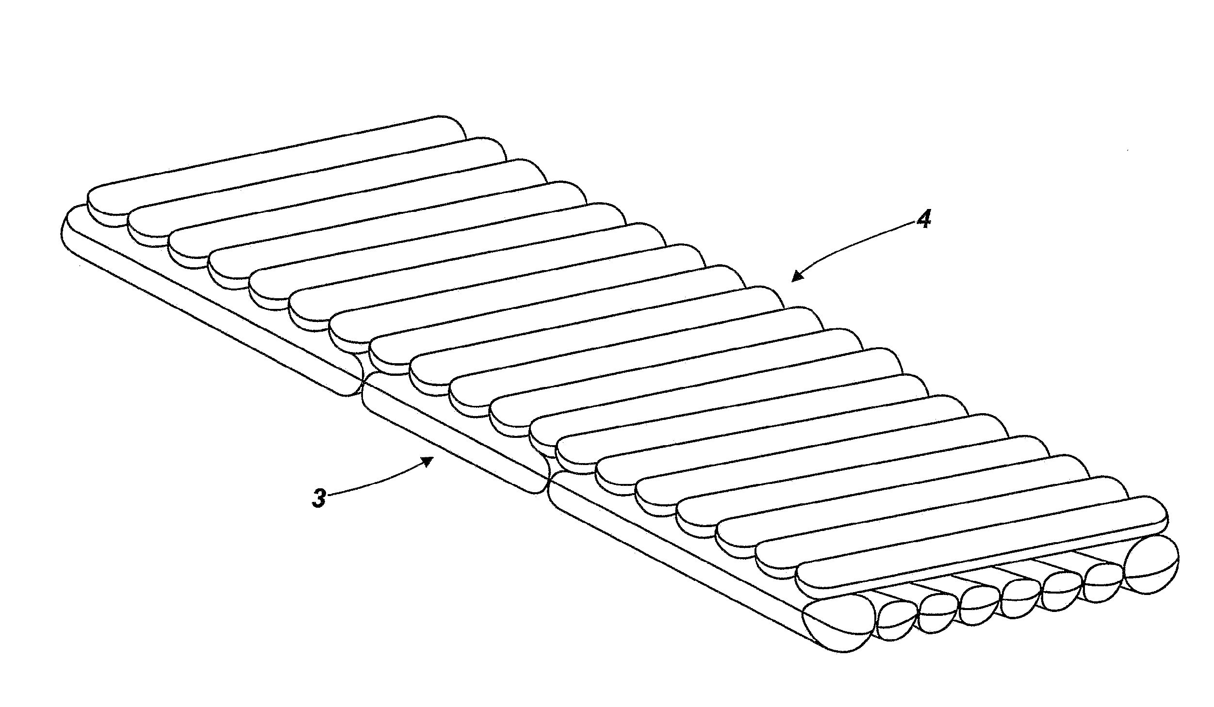
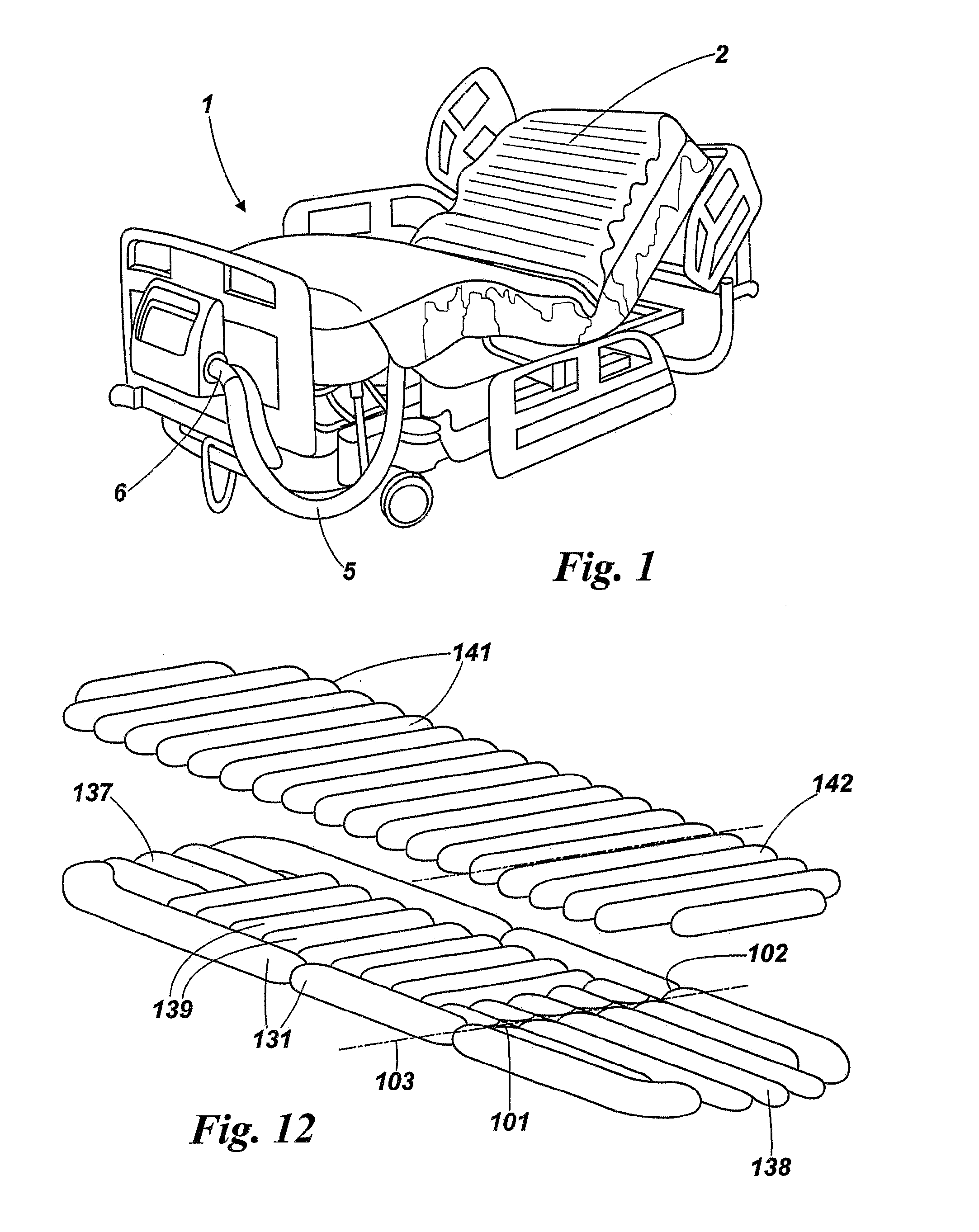
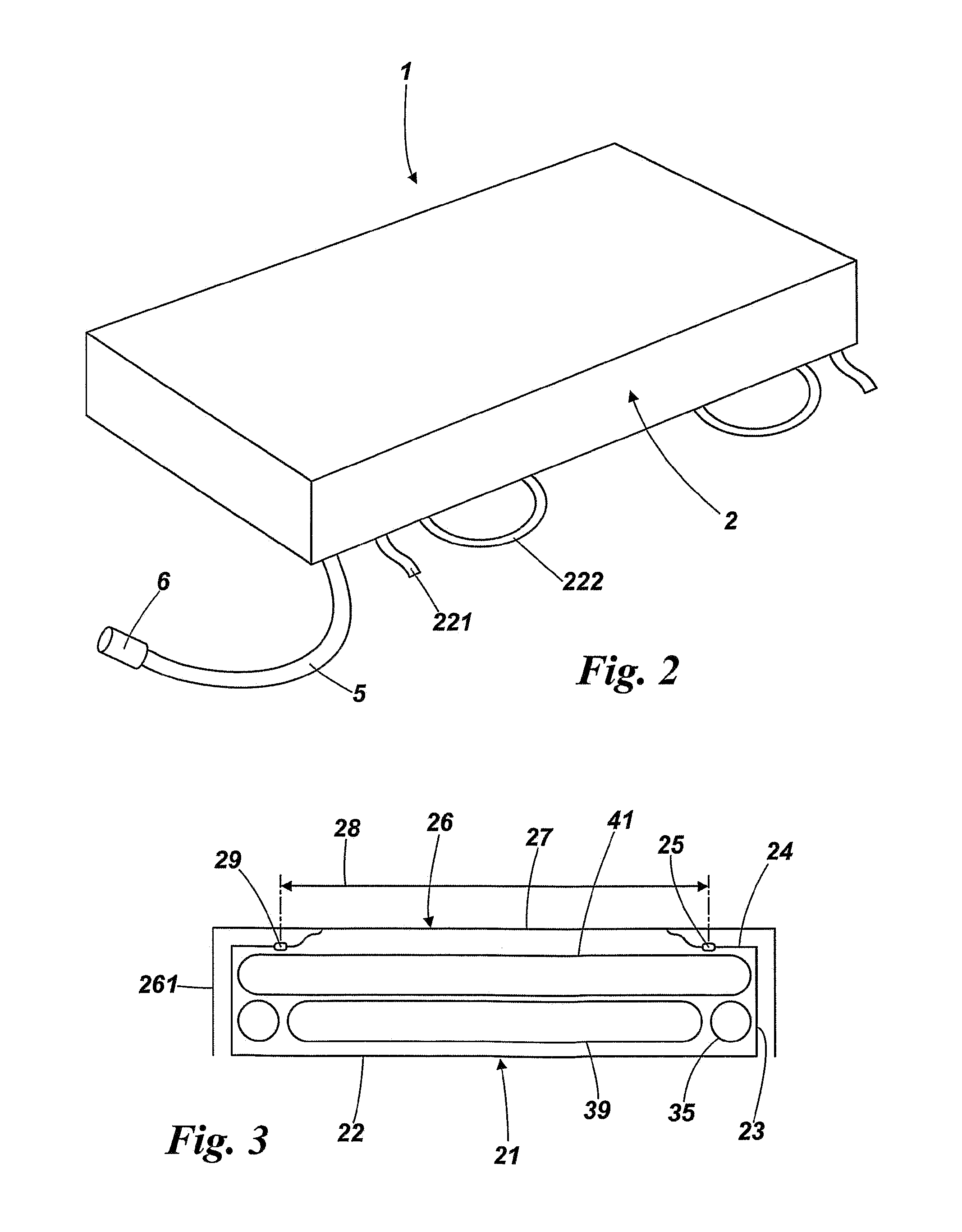
Referring to the drawings, a mattress 1 has a cover 2 enclosing two layers 3, 4 of pneumatic cells. The cells are made of impermeable sheet or tube material welded into desired shapes, typically of polyurethane material. The manner in which the cells are made is conventional, known to the skilled reader and will not be described here.

The bottom layer comprises edge cells 31 extending the full length of the mattress. These cells are closed at two positions, a hip position 32 and a knee position 33. Thus these cells have a head and back portion 34, an upper leg portion 35 and a lower leg portion 36. The portions can hinge or pivot with respect to their adjoining portions, without the pneumatic pressure in them tending to keep them rigid. Between the edge cells at the head end of the bed, i.e. between the head portions 34, six short head cells 37 are arranged with their cell length in the direction of the length of the mattress. The head cells are manufactured as a group separate from ...


PUM


Abstract

A mattress has a cover enclosing two layers of pneumatic cells made of impermeable material welded into desired shapes. A bottom layer comprises edge cells extending the length of the mattress, partially closed at hip and knee positions so the cells have head and back, upper leg and lower leg portions that pivot relative to adjoining portions, without pressure in them tending to keep them rigid. Six head cells are arranged with their length in the direction of the length of the mattress, separate from the edge cells. Six lower leg cells are between the lower leg portions. A central space in the bottom layer is filled by a group of nine transversely extending cells held together by toggles. An upper layer has a head back and upper leg group of twelve transverse cells and a second group of seven lower leg cells.

Description

BACKGROUND OF THE INVENTIONThe present invention relates to a pneumatic mattress.A pneumatic mattress is a mattress having a plurality of pneumatic cells which are so connected that sets of them can be selectively and cyclically pressurized and exhausted—or inflated and deflated—in sequence to support a user, normally a patient liable to suffer or actually suffering from pressure sores. Cycling the mattress simulates movement that a patient would make if fit and healthy so as to avoid supporting his / her weight in the same place all the time. Pneumatic mattress design suffers from a dichotomy that separate independent cells held together only by an outer cover make for simplicity and cheapness, whereas integrally fabricated and smaller cells provide support in such a way that portions of the patient's anatomy are not liable to slip between two pressurized cells when an intervening one is deflated.Pneumatic mattresses are usually pressurized with air drawn from the ambient atmosphere....

Claims


Application Information

Patent Timeline
IPC IPC(8): A47C27/10
CPCA61G7/05776
Inventor PILE, BRIAN FRANK
Owner LINET SPOL
Why Eureka
Try Eureka