Shaft seal

a shaft seal and seal technology, applied in the field of shaft seals, can solve the problems of increasing the risk of coking, inundation of the entire piston ring groove, and serious wear and tear of the shaft seals

Active Publication Date: 2011-10-13
TURBO SYST SWITZERLAND LTD
View PDF6 Cites 15 Cited by
  • Summary
  • Abstract
  • Description
  • Claims
  • Application Information

AI Technical Summary

Problems solved by technology

The lubricating oil which issues from the radial bearing possibly splashes axially into the piston ring region of the gas seal and in the most unfavorable case floods the entire piston ring groove.
Thus, a positive pressure difference (pressure in the flow passage is higher than in the cavity of the bearing housing) results in the ensuing gas leakage blowing through the piston ring seal, and the bearing oil which has inadvertently penetrated into the piston ring region is carried back into the oil-collecting chamber of the bearing housing.
In the case of t...

Method used


Image

  • Shaft seal
  • Shaft seal
  • Shaft seal

Examples


Embodiment Construction

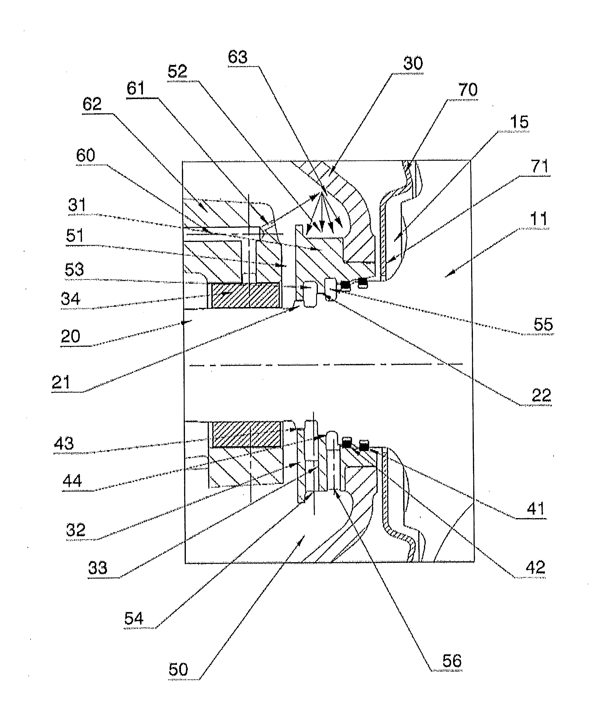
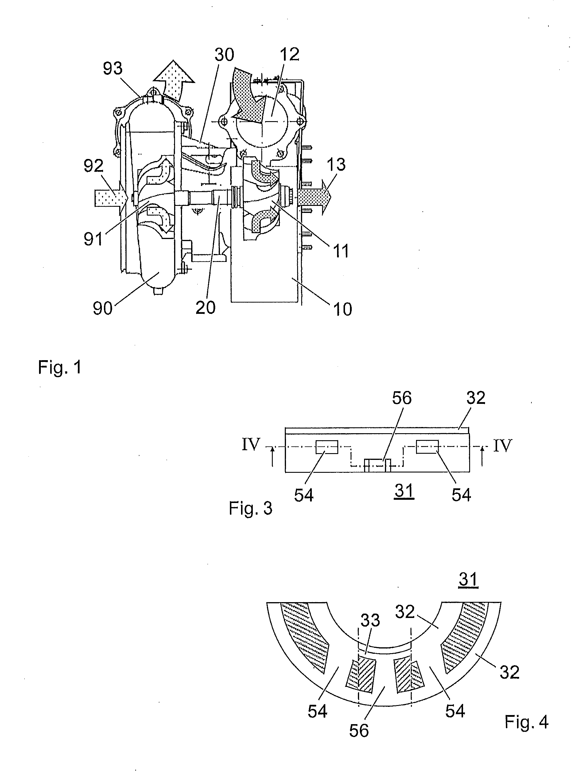
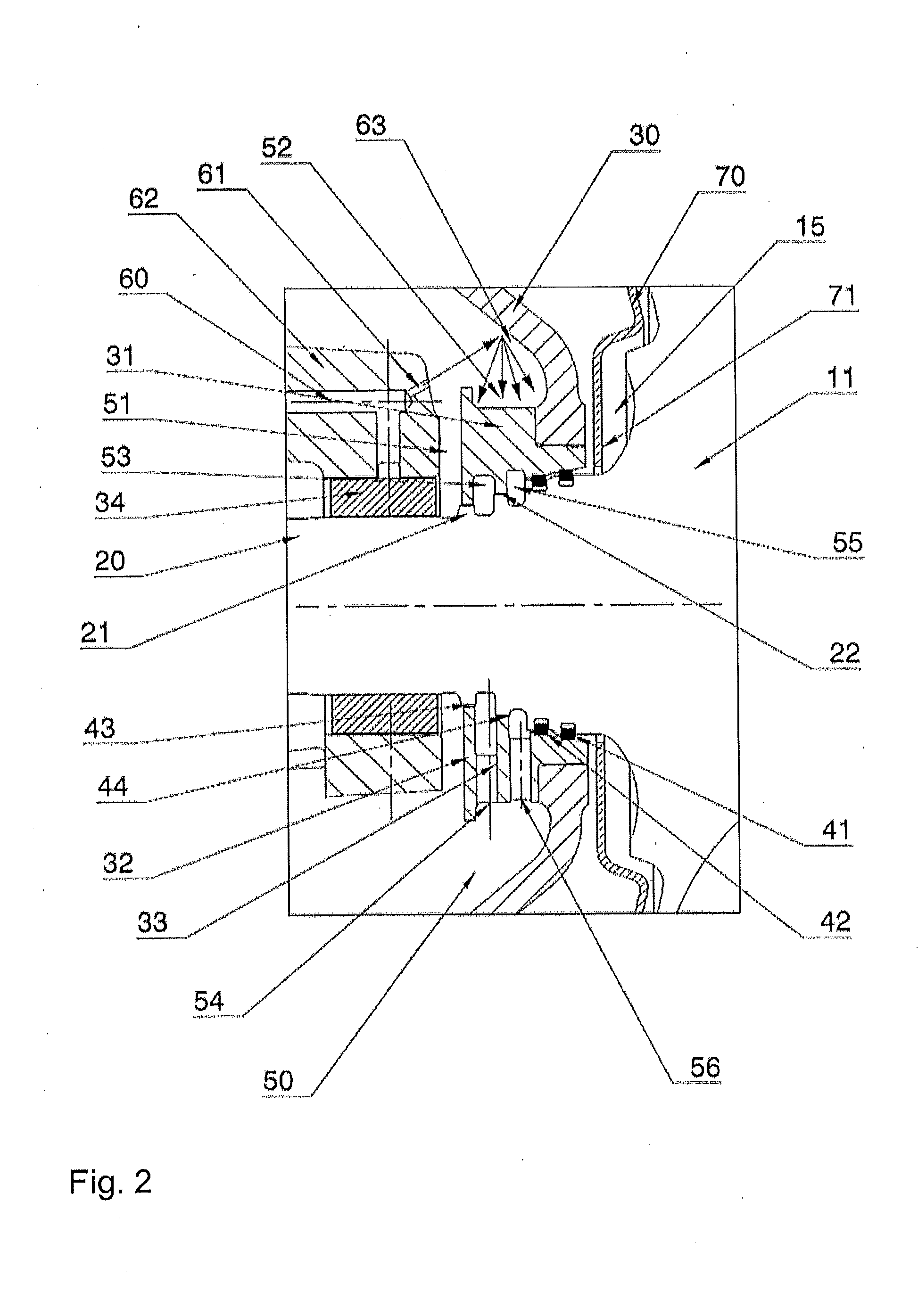
[0023]Exemplary embodiments of the present disclosure provide a shaft seal of a shaft—supported in a bearing housing—of a turbomachine, in which the draining behavior of the lubricating oil is improved and the risk of coking of the piston ring seal is minimized by means of active cooling of the sealing section.

[0024]According to an exemplary embodiment of the present disclosure, the shaft seal, which is supported in a bearing housing, of a turbomachine between a cavity in the bearing housing and a wheel back space of a rotating wheel of the turbomachine, includes multiple seals. A first, rotating wheel-side seal can be designed in the form of at least one piston ring, for example, and a second, bearing-side seal can be designed in the form of a sealing gap, for example, between the bearing housing and the shaft. Arranged between the rotating wheel-side seal and the bearing-side seal is an oil outlet chamber which is delimited by a third, center seal, which is designed in the form of...


PUM


Abstract

A shaft seal of the rotating wheel shaft of a turbomachine includes a rotating wheel-side seal and a bearing-side seal between the bearing housing and the shaft. An oil outlet chamber is arranged between the rotating wheel-side seal and the bearing-side seal. The oil outlet chamber is delimited by a third seal between the bearing housing and the shaft, and a gas discharge chamber is arranged between the third seal and the rotating wheel-side seal. The construction is actively cooled by means of at least one splash oil bore in the region of the oil drain channel, as a result of which coking of the shaft seal can be prevented. The third seal separates the oil issuing from the oil outlet chamber from the gas issuing from the gas discharge chamber.

Description

RELATED APPLICATIONS[0001]This application claims priority under 35 U.S.C. §119 to European Patent Application No. 102010003796.6 filed in Europe on Sep. 4, 2010, the entire content of which is hereby incorporated by reference in its entirety.FIELD[0002]The present disclosure relates to the field of turbomachines. More particularly, the present disclosure relates to the field of exhaust gas turbochargers which are exposed to admission of exhaust gases from internal combustion engines. The present disclosure also relates to a shaft seal of such a turbomachine.BACKGROUND INFORMATION[0003]Exhaust gas turbochargers are known to be used for increasing the power of an internal combustion engine. In such an exhaust gas turbocharger, a turbine is provided in the exhaust gas path of the internal combustion engine, and a compressor is arranged upstream of the internal combustion engine, which is connected to the turbine via a common shaft. With charging of an internal combustion engine by mea...

Claims


Application Information

Patent Timeline
IPC IPC(8): F04D29/10F16J9/00F16J15/16
CPCF05D2220/40F01D11/003F01D25/125F01D25/183F05D2240/58F05D2260/205F02B39/00F01D25/16F01D25/18F02B39/14
Inventor SCHLIENGER, JOELKIES, MATTHIASABERLE, PATRICKMUNDINGER, GERD
Owner TURBO SYST SWITZERLAND LTD
Why Eureka
Try Eureka