
Assembly, system, and method for cable tension measurement

a technology of tension measurement and cable, applied in the direction of tension measurement, force/torque/work measurement, instruments, etc., can solve problems such as damage to winch cables

Inactive Publication Date: 2011-10-13
SCHLUMBERGER TECH CORP
View PDF3 Cites 28 Cited by
  • Summary
  • Abstract
  • Description
  • Claims
  • Application Information

AI Technical Summary

Benefits of technology

The patent describes a device that can measure the tension force in a cable as it is being deployed from a spooling device. The device includes a force sensor that measures the force applied to the spooling device, and a cable sensor that measures the spooling / unspooling characteristics of the cable. By calculating the tension force in the cable based on these measurements, the device can help ensure that the cable is properly tensioned and can safely be used for its intended purpose.

Problems solved by technology

In certain instances, a conventional strain gauge has shown some reliability issues and the wheels of the CMTD can damage the winch cable (under high tension the CMTD could even break the cable).

Method used


Image

  • Assembly, system, and method for cable tension measurement
  • Assembly, system, and method for cable tension measurement
  • Assembly, system, and method for cable tension measurement

Examples


Embodiment Construction

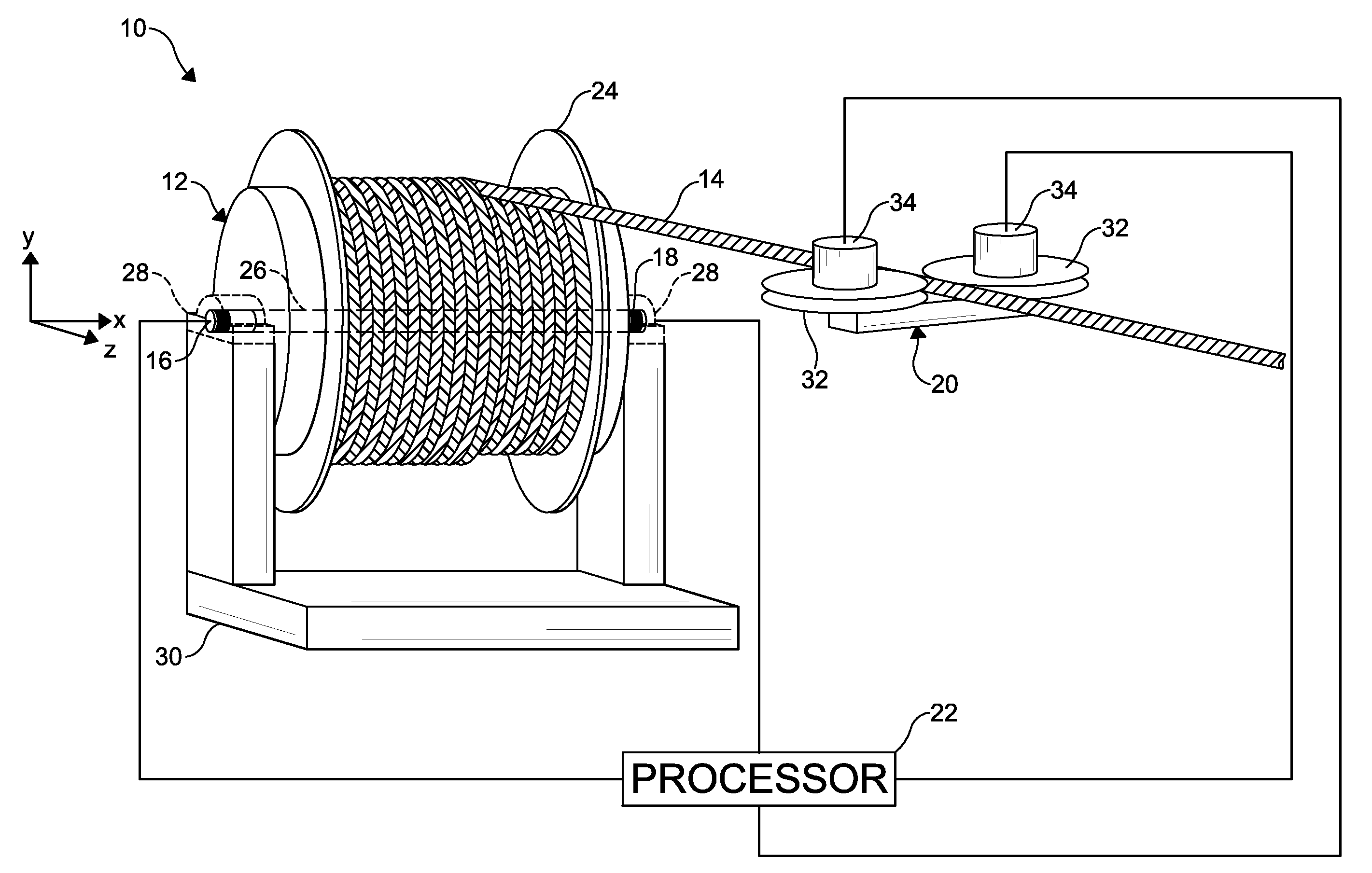
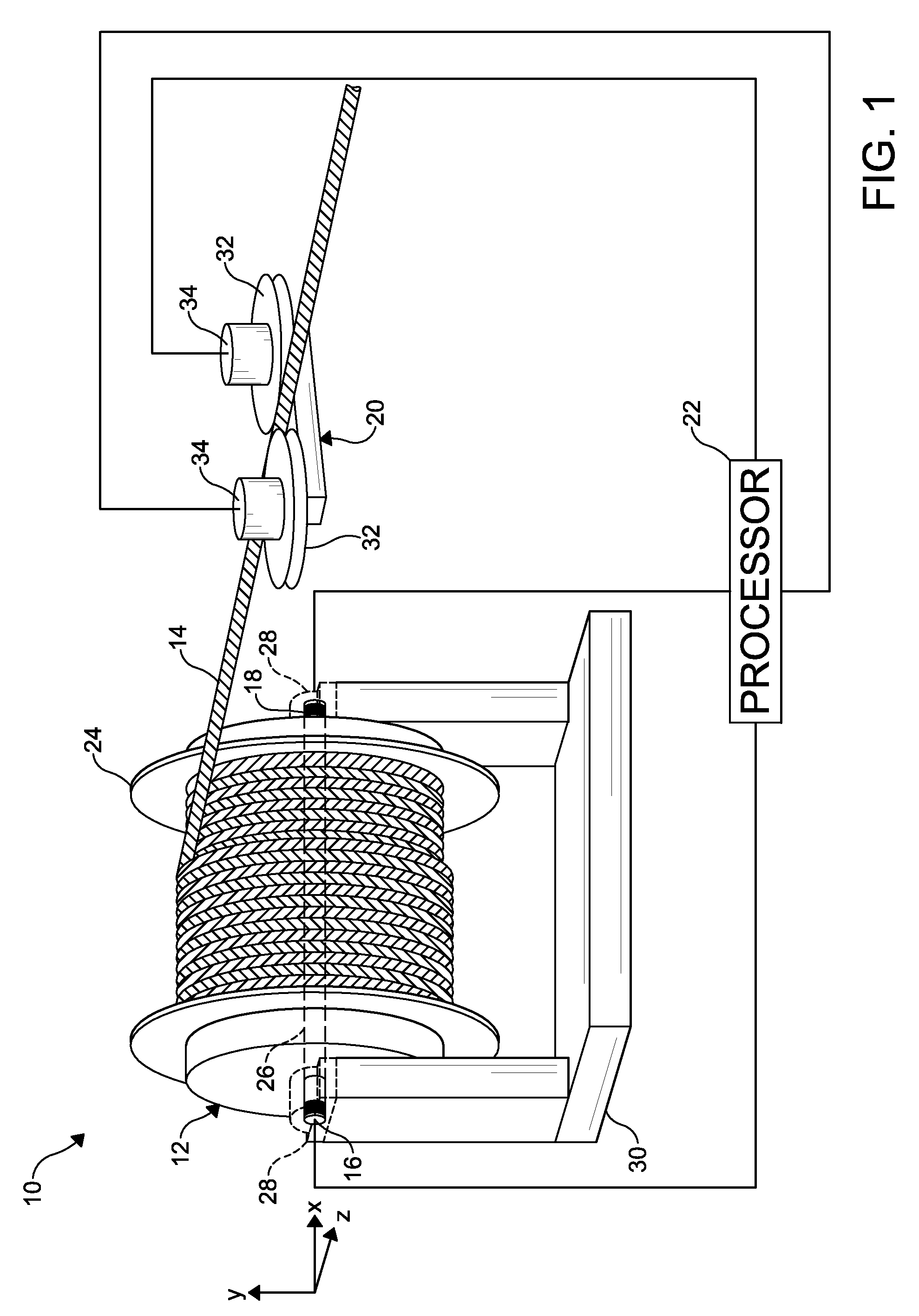
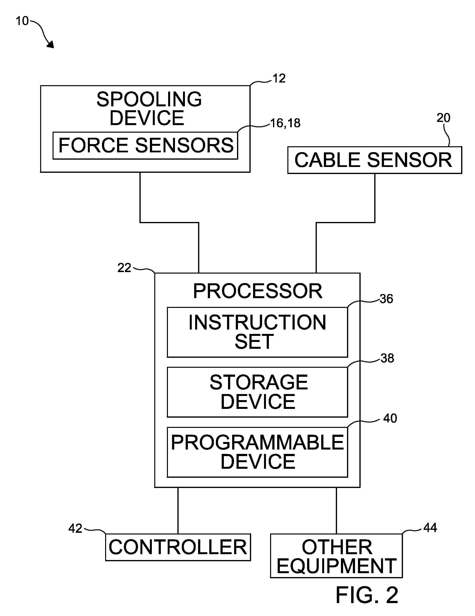
Referring now to FIGS. 1-2, there is shown an embodiment of a tension measurement system, indicated generally at 10. As shown, the tension measurement system 10 includes a spooling device 12 for spooling a cable 14, a plurality of force sensors 16, 18 positioned to measure forces acting on the spooling device 12, a cable sensor 20, and a processor 22 in communication with the force sensors 16, 18 and the cable sensor 20. Those skilled in the art will appreciate that the cable 14 may comprise a wireline electrical or electro-optical cable, a slickline cable, a length of coiled tubing, or a similar suitable spoolable device that is operable to be spooled onto the spooling device 12.

As shown in FIG. 1, the spooling device 12 includes a drum 24 having a shaft 26 (i.e. support member) disposed therethrough, wherein a portion of the shaft 26 extends from opposites sides of the drum 24. A pair of bearings 28 are disposed on a chassis 30 (e.g. cradle) and positioned to receive the portion o...


PUM

PropertyMeasurementUnit
tension measurementaaaaaaaaaa
tension forceaaaaaaaaaa
forceaaaaaaaaaa

Abstract

A tension measurement assembly, for measuring and monitoring a tension force in a cable being deployed from a spooling device on which the cable is spooled, comprises at least one force sensor disposed adjacent the spooling device for sensing a force applied to the spooling device and generating a force signal representing the sensed force, and a processor responsive to the force signal for calculating and monitoring a tension force present in the cable. A cable sensor engages the deployed cable for sensing a spooling / unspooling rate and a length of the cable moving past the cable sensor in a pre-determined time period and generating a spooling signal representing the sensed rate and length to the processor for use in the calculating and monitoring of the tension force.

Description

BACKGROUND OF THE INVENTIONThe statements in this section merely provide background information related to the present disclosure and may not constitute prior art.The present invention generally relates to wellsite surface equipment such as wireline surface equipment and the like. In particular, the invention is directed to an assembly, a system, and a method for measuring a tension in a cable.During a typical wireline operation a tool string is moved up and down in a well using a winch. Specifically, the tool string is attached to a cable, whereby the cable is spooled / unspooled on a drum. In this context, it is critical to monitor a tension in the cable to prevent operational pitfalls such as cable breaks (e.g. tool string stuck into the well), cable slacking (e.g. not enough cable tension), and the like.Currently, cable tension is measured using a Cable Mounted Tension Device (CMTD), wherein the cable is trapped between three wheels and a shaft is deformed proportionally to the ca...

Claims


Application Information

Patent Timeline
Patent Type & Authority Applications(United States)
IPC IPC(8): G01L5/04
CPCG01L5/04G01L5/103
Inventor TEURLAY, LUCASBREARD, STEPHANEAUBRY, DOMINIQUE
Owner SCHLUMBERGER TECH CORP
Learn More