Concealment Headwear

a technology of visors and visors, applied in the field of head wear, can solve the problems of insufficient support of the visor in the desired angular orientation of the wire rim, the design suffers from a significant shortcoming, and the wire rim is not secured about the outer perimeter of the visor, etc., to achieve the effect of preventing sagging, ensuring maximum visibility and sufficient rigidity

Inactive Publication Date: 2011-10-20
SCOTT GERALD C
View PDF7 Cites 16 Cited by
  • Summary
  • Abstract
  • Description
  • Claims
  • Application Information

AI Technical Summary

Benefits of technology

[0009]It is, therefore, a primary object of the subject invention to provide improved head wear wherein the visor is adapted to provide concealment for the wearer and yet allows maximum visibility overhead without upward head movement.
[0010]It is another primary object of the subject invention to provide improved head wear of the aforementioned type and comprising a head-mountable portion and a see-through visor portion, the latter being comprised of a framing member suitable for supporting the visor in a desired angular orientation relative to the head-mountable portion such that sagging is prevented.
[0011]It is yet another object of the subject invention to provide improved head wear of the aforementioned type wherein the visor portion is malleable to form the shape desired by the wearer, yet having sufficient rigidity to substantially maintain its original shape and orientation relative to the head-mountable portion.
[0012]It is also an object of the subject invention to provide improved head wear comprised of relatively few components to facilitate easy assembly and use as well as reduce the chances of mechanical failure.
[0013]Another object of the subject invention is to provide improved head wear which is relatively simple in design and therefore capable of rapid construction at relatively low costs.

Problems solved by technology

Such a design, however, suffers from a significant shortcoming.
Namely, the wire rim secured about the outer perimeter of the visor fails to provide a sufficient support for the mesh panel.
Accordingly, the wire rim proved unable to support the visor in the desired angular orientation relative to the wearer's forehead, often sagging over the wearer's face.
Moreover, the wire rim of the '720 apparatus too easily disfigured to maintain the desired shape of the visor.

Method used


Image

  • Concealment Headwear
  • Concealment Headwear
  • Concealment Headwear

Examples


Embodiment Construction

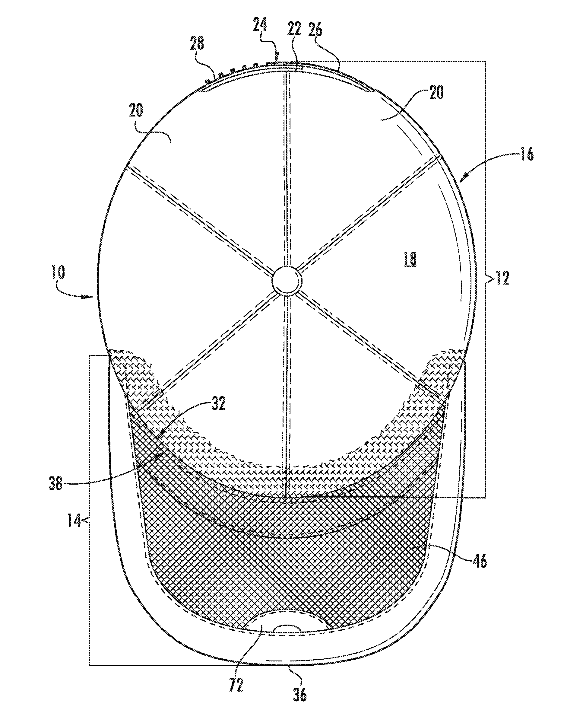
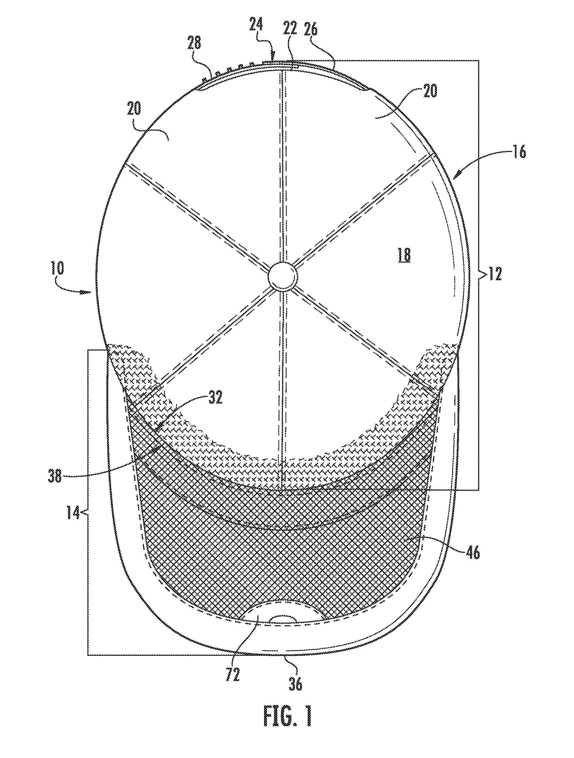
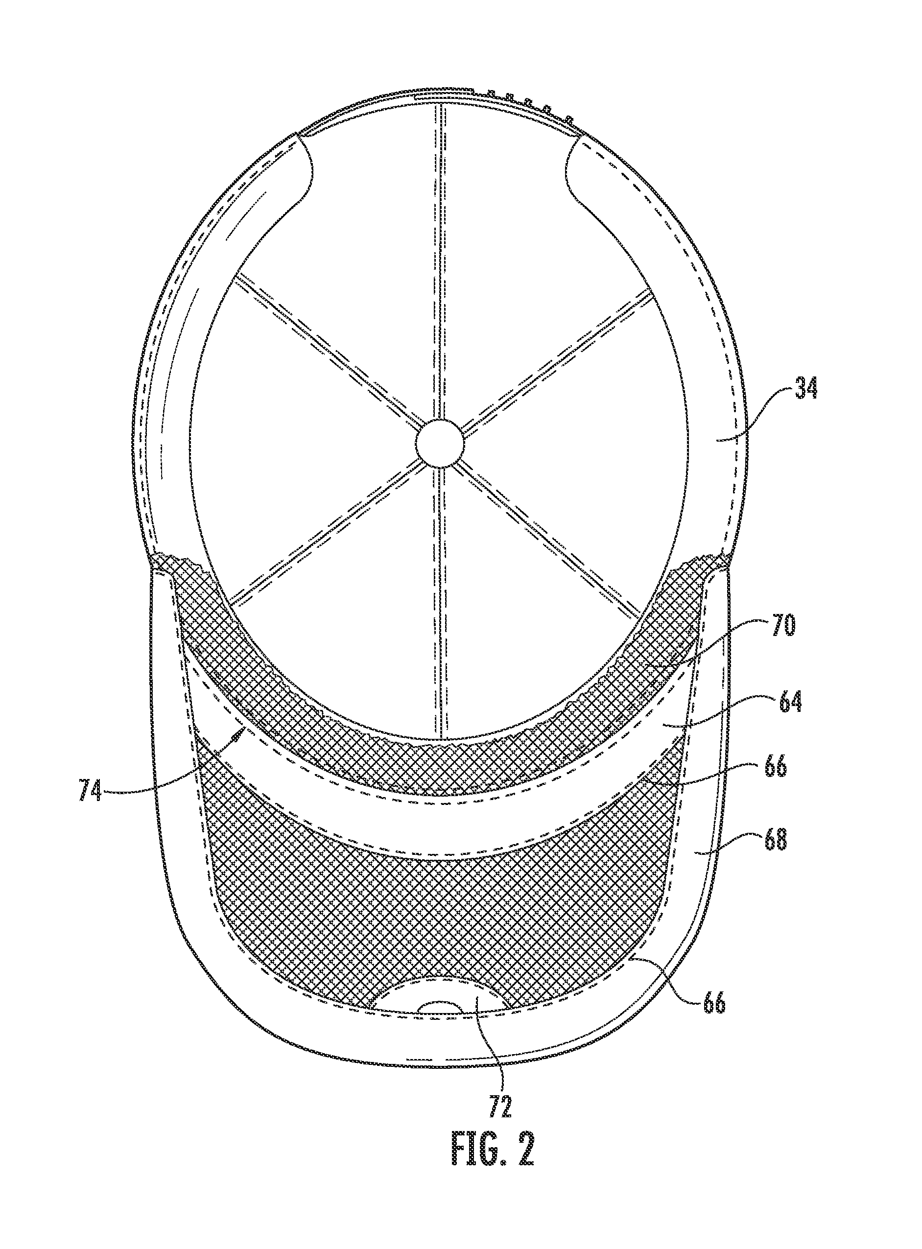
[0021]At the outset, it should be clearly understood that like reference numerals are intended to identify the same structural elements, portions or surfaces consistently throughout the several drawings figures, as such elements, portions or surfaces may be further described or explained by the entire written specification, of which this detailed description is an integral part. Unless otherwise indicated, the drawings are intended to be read (e.g., cross-hatching, arrangement of parts, proportion, degree, etc.) together with the specification, and are to be considered a portion of the entire written description of this invention. As used in the following description, the terms “horizontal” and “vertical” simply refer to the orientation of an object relative to level ground, and the terms “left”, “right”, “top” and “bottom”“up” and “down”, as well as adjectival and adverbial derivatives thereof (e.g., “rightwardly”, “upwardly”, etc.), simply refer to the orientation of a surface rel...


PUM


Abstract

Head wear for providing partial concealment of the wearer while simultaneously allowing visibility therethrough, the apparatus comprising, a head-mountable portion and a visor portion, the visor portion comprising a generally crescent-shaped framing member defining a generally crescent-shaped opening, the opening being covered with a foraminous see-through mesh bound to the framing member with a cloth binding. The framing member is constructed of a semi-flexible and malleable material, preferably but not essentially a plastic which may be formed, stamped or cut into the desired shape. At least two embodiments of the invention are provided, namely a compression fitted visor and a baseball type cap. The apparatus is useful for hunters of foul as well as law enforcement personnel engaged in covert operations.

Description

FIELD OF THE INVENTION[0001]The subject invention relates generally to head wear and more particularly to head wear of the variety including a foraminous mesh visor to partially conceal the wearer's face from view while permitting the wearer to see therethrough (hereinafter “concealment headwear”). The subject invention has utility in hunting and law enforcement applications among others.BACKGROUND OF THE INVENTION[0002]Heretofore, caps specially designed for hunters of foul have been provided to provide a degree of concealment from prey while permitting the wearer to see through the visor portion thereof. Applicant's U.S. Pat. No. 5,159,720 issued in November 1992 and entitled, Hunter's Hat, teaches a cap with a see-through nylon mesh visor having a dull camouflage pattern that matches the rest of the hat to provide undetectable cover from above. By looking through the mesh front, a hunter is able to see the water fowl as it comes into view while the hunter's face is still being hi...

Claims


Application Information

Patent Timeline
Patent Type & Authority Applications(United States)
IPC IPC(8): A42B1/04A42B1/00
CPCA42B1/062A42B1/0182
Inventor SCOTT, GERALD C.
Owner SCOTT GERALD C
Why Eureka
Try Eureka