Vital signs monitor using an optical ear-based module

a monitor and optical ear technology, applied in the field of cuffless monitors, can solve the problems of reducing the accuracy of measurement, motion-related artifacts, etc., and achieve the effects of low signal-to-noise ratio, less motion, and less motion-related artifacts

Inactive Publication Date: 2006-06-08
TRIAGE WIRELESS
View PDF93 Cites 117 Cited by
  • Summary
  • Abstract
  • Description
  • Claims
  • Application Information

AI Technical Summary

Benefits of technology

[0012] The invention has many advantages. In particular, during day-to-day activities, a patient's ear undergoes significantly less motion than the patient's finger. This means a plethysmograph measured from the ear has a relatively high signal-to-noise ration and contains relatively few motion-related artifacts. When processed with the algorithm described herein, this results in an accurate, continuous measurement of blood pressure, heart rate, and pulse oximetry. Moreover, because the ear is closer to the heart than a finger, a pulse oximetry measurement made in this region is likely to correlate better with blood pressure. The optical ear module is comfortable, unobtrusive, and can easily be worn for a short (e.g. 24-hour period) without affecting the patient.
[0013] The cuff-less blood pressure-measuring device of the invention combines all the benefits of conventional cuff-based blood-pressure measuring devices without any of the obvious drawbacks (e.g., restrictive, uncomfortable cuffs). Its measurement is basically unobtrusive to the patient, and thus alleviates conditions, such as a poorly fitting cuff, that can erroneously affect a blood-pressure measurement.
[0015] These same features mean the device can also be used in ‘telemedicine’ applications where measurements are made from a remote patient and wirelessly transmitted to a central, Internet-accessible computer. In this way patients with cardiac conditions can be characterized remotely over extended periods of time. This characterization, for example, can be made by a medical professional using a remote, Internet-accessible website.

Problems solved by technology

This generates ‘noise’ in the plethysmograph, which in turn can lead to motion-related artifacts in data describing pulse oximetry and heart rate.
Ultimately this reduces the accuracy of the measurement.

Method used


Image

  • Vital signs monitor using an optical ear-based module
  • Vital signs monitor using an optical ear-based module
  • Vital signs monitor using an optical ear-based module

Examples


Embodiment Construction

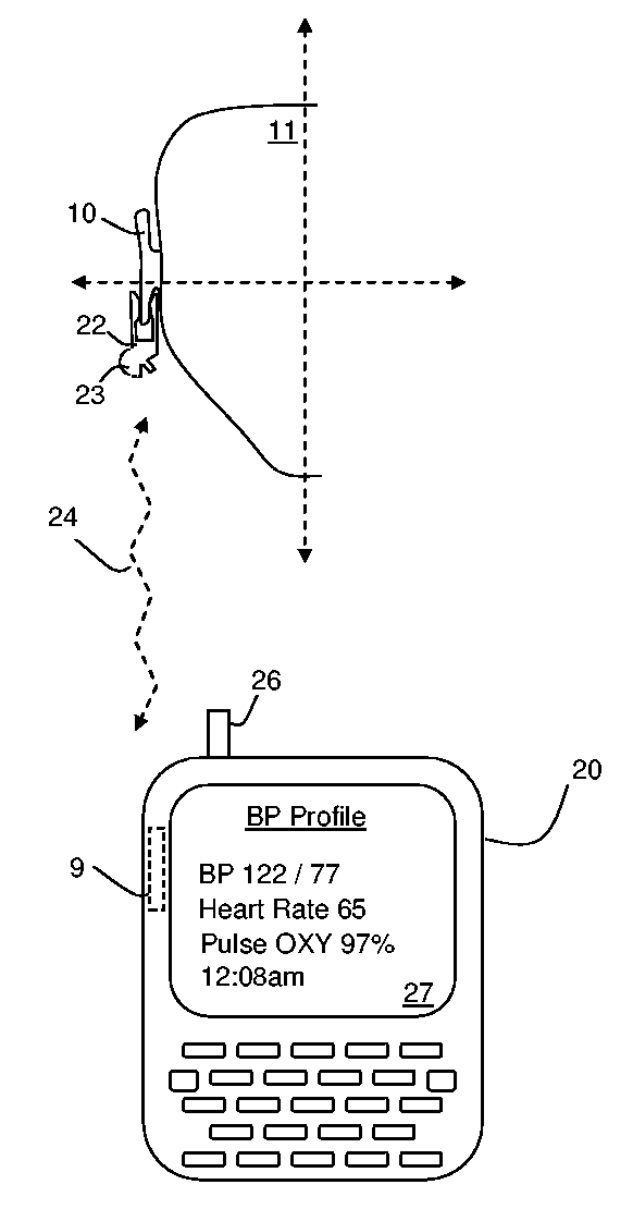
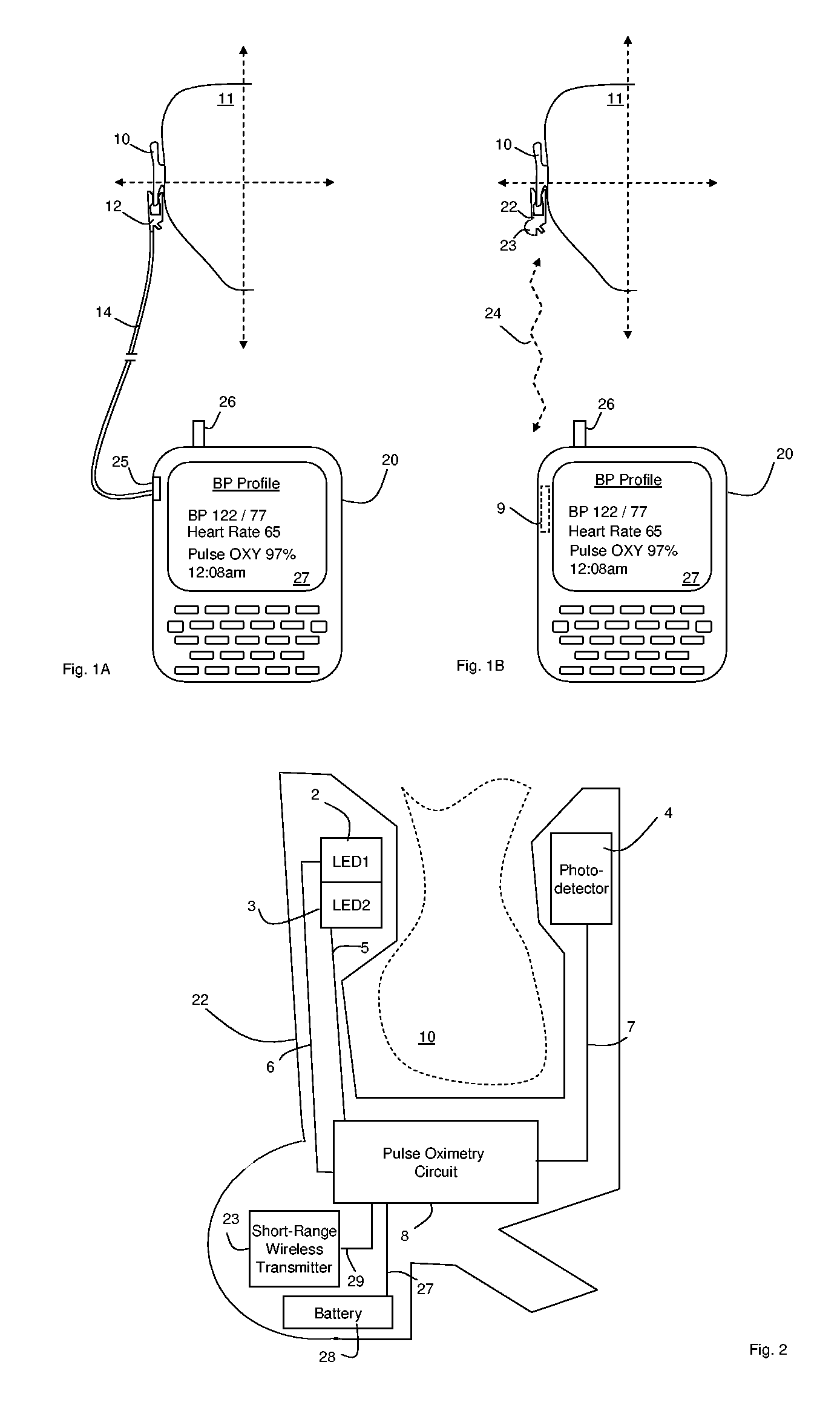
[0024]FIG. 1A shows an optical ear module 12 and wireless hub 20 for measuring vital-sign information (e.g., blood pressure, pulse oximetry, and heart rate) from an ear 10 of a patient 11. The optical ear module 12 clamps onto a lobe of the patient's ear 10 to make the measurement. An electric cable 14 connects the optical ear module to the wireless hub 20, which is typically worn around the patient's belt or arm like a portable radio. The optical ear module 12 features a pair of LEDs (described in detail with reference to FIG. 2) that generate, respectively, red and infrared radiation. A photodetector detects transmitted and scattered radiation and send this information to a microprocessor, which analyzes it as described in detail below to determine the vital signs.

[0025] The wireless hub 20, which can be a conventional cellular telephone or personal digital assistant, includes a serial port 25 that receives vital-sign information from the optical ear module 12 through the cable 1...


PUM


Abstract

The invention provides a system for measuring blood pressure from a patient that includes: 1) an optical module configured to be worn on the patient's ear and comprising at least one optical source and a photodetector; 2) a calibration source configured to make a blood pressure measurement; and, 3) a processing module configured to: i) receive a first signal from the optical module; ii) receive a second signal from the calibration source; iii) process the first and second signals to generate a calibration table; and iv) receive a third signal from the optical module and compare it to the calibration table to determine the patient's blood pressure.

Description

CROSS REFERENCES TO RELATED APPLICATION [0001] Not Applicable DESCRIPTION [0002] 1. Background of the Invention [0003] The present invention relates to medical devices for monitoring vital signs such as heart rate, pulse oximetry, and blood pressure. [0004] 2. Description of the Related Art [0005] Pulse oximeters are medical devices featuring an optical module, typically worn on a patient's finger or ear lobe, and a processing module that analyzes data generated by the optical module. The optical module typically includes first and second light sources (e.g., light-emitting diodes, or LEDs) that transmit optical radiation at, respectively, red (λ˜630-670 nm) and infrared (λ˜800-1200 nm) wavelengths. The optical module also features a photodetector that detects radiation transmitted or reflected by an underlying artery. Typically the red and infrared LEDs sequentially emit radiation that is partially absorbed by blood flowing in the artery. The photodetector is synchronized with the ...

Claims


Application Information

Patent Timeline
Patent Type & Authority Applications(United States)
IPC IPC(8): A61B5/02A61B5/00
CPCA61B5/021A61B5/14552A61B5/1495A61B5/6814A61B5/6816
Inventor BANET, MATTHEW JOHNMORRIS, BRETT GEORGEVISSER, HENK
Owner TRIAGE WIRELESS
Why Eureka
Try Eureka