System, method, and apparatus for removing covers from shipping containers

a technology for shipping containers and covers, applied in the field of efficient packaging of products, can solve the problems of repeated motion injury of operators and cover breakage, and achieve the effect of reducing motion injury, reducing breakage, and removing covers quickly and quickly

Inactive Publication Date: 2006-09-28
HITACHI GLOBAL STORAGE TECH NETHERLANDS BV
View PDF17 Cites 2 Cited by
  • Summary
  • Abstract
  • Description
  • Claims
  • Application Information

AI Technical Summary

Benefits of technology

[0007] One embodiment of a system, method, and apparatus for easily and quickly removing covers from shipping cassettes that are used to ship computer disk media is disclosed. This solution unlatches the covers and separates them from the cassette in a single fixture position with fewer motions and with less breakage. The present invention uses a movable fork to unlatch one end of the top cover from the bottom cover while the cassette is rotated off of the other end of the bottom cover. This action unlatches and separates the two covers to remove the bottom cover from the cassette in one motion. The top cover is then easily lifted off of the bottom cover. The advantage of this tool is that the unlatching and cover removal can be done in one motion on a single fixture position instead of having to move the cassette between two separate positions on a fixture. It also reduces the number of broken covers by ensuring that the covers are unlatched prior to separating and removing them.
[0008] To use the tool, the cassette is placed between the side walls, either on top of a pair of guide rails (e.g., for a 95 mm, 84 mm, or 70 mm cassette), or in a slot between the guide rails (e.g., 65 mm cassette). The cassette is moved forward until it contacts the front of the catch and is then rocked down on top of the fork. As the covers move down on the fork, the slope of the fork pulls the top cover forward and unlatches it from the bottom cover. The fork is mounted to a spring-loaded slide, so that the now-unlatched cover and the cassette are slid forward. This slides the bottom cover under the catch. The cassette is then rocked backward over the inner guide rails and the bottom cover is pried off of the cassette. The cassette is pulled off the tool toward the rear and operator catches the loose bottom cover and removes it from the latch on the other end of the cassette. The top cover is then easily lifted off and the contents of the cassette made accessible.

Problems solved by technology

However, manual removal of the covers 15, 17 on a large volume basis is a probable source of repetitive motion injury to the operators. FIG. 14 depicts a prior art fixture 31 for removing the covers 15, 17 from body 13.
Unfortunately, this prior art design is a potential source of cover breakage (e.g., tabs 19 and clasps 21) and requires multiple hand motions to unlatch the covers before they are removed from the cassettes.

Method used


Image

  • System, method, and apparatus for removing covers from shipping containers
  • System, method, and apparatus for removing covers from shipping containers
  • System, method, and apparatus for removing covers from shipping containers

Examples


Embodiment Construction

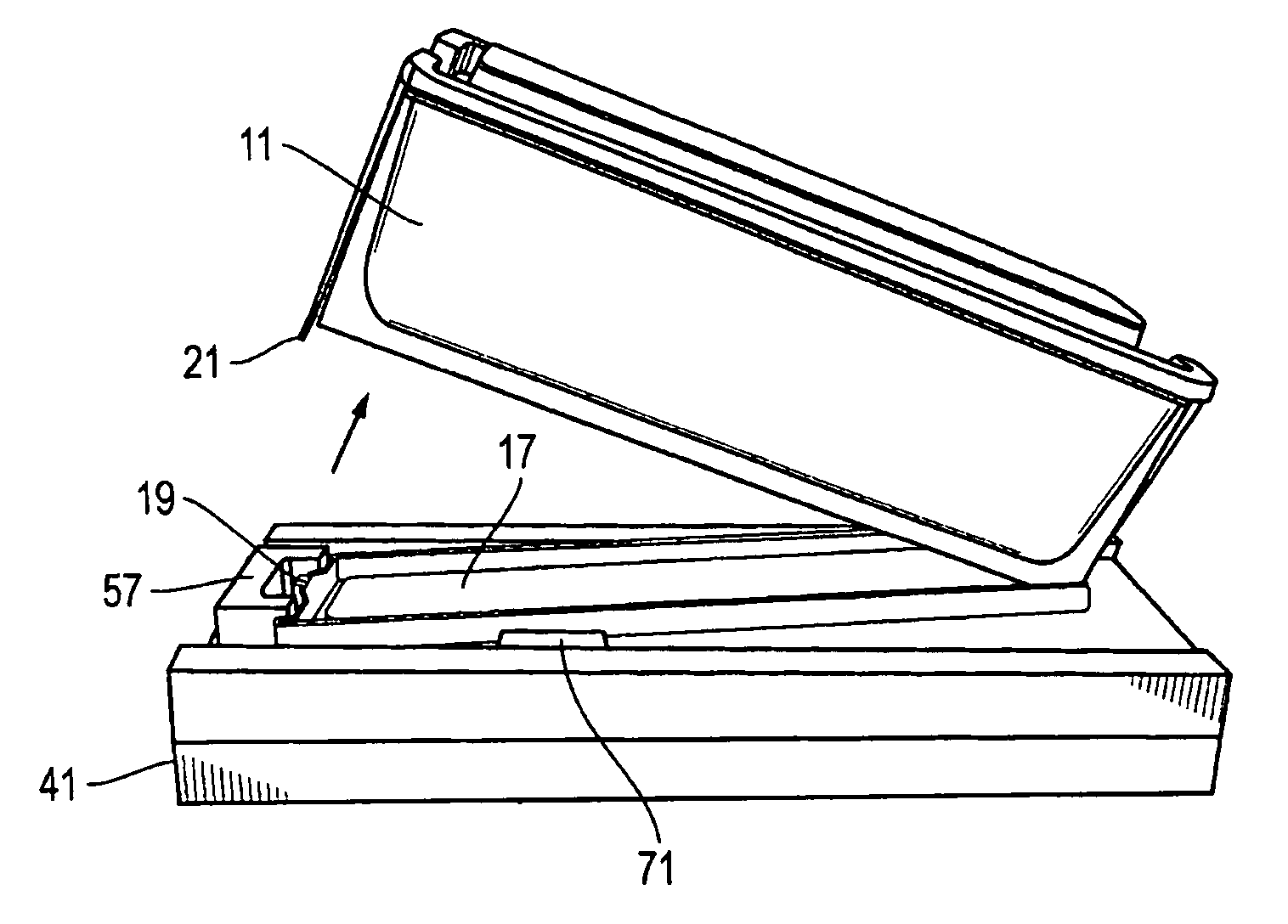
[0025] Referring to FIGS. 3-13, one embodiment of a system, apparatus, and method for removing a cover from a shipping container is disclosed. The apparatus comprises a fixture 41 (FIGS. 3 and 4) having a base 43 with a longitudinal axis 45, a lateral axis 47 orthogonal to the longitudinal axis 45, and a transverse (i.e., vertical) axis 49 orthogonal to both the longitudinal and lateral axes 45, 47. A surface 50 extends in a plane defined by the longitudinal and lateral axes 45, 47. Side walls 51 extend transversely (i.e., vertically) from the surface 50, and a slot 53 is defined longitudinally between the side walls 51 and extends along the surface 50 for supporting the cassette or shipping container 11.

[0026] In one embodiment, a pivot guide 55 is mounted to the surface 50 and extends laterally between the side walls 51. The pivot guide 55 guides the shipping container 11 and acts as a fulcrum for pivoting of the shipping container 11 during cover removal. A catch 57 is mounted t...


PUM


Abstract

A system for removing covers from shipping cassettes that are used to ship computer disk media unlatches the covers and separates them from the cassette in a single fixture position. A movable fork unlatches a top cover from a bottom cover while the cassette is rotated off of the bottom cover. This action unlatches and separates the two covers allowing the removal of the bottom cover from the cassette in one motion. The top cover is then easily lifted off of the bottom cover.

Description

BACKGROUND OF THE INVENTION [0001] 1. Technical Field [0002] The present invention relates in general to efficiently handling the packaging of products and, in particular, to an improved system, method, and apparatus for removing the covers from shipping containers of computer disk media. [0003] 2. Description of the Related Art [0004] Referring to FIGS. 1 and 2, a typical shipping container or cassette 11 for holding a plurality of workpieces 12 (e.g., computer disk media) is shown. The cassette 11 has a main body 13 that engages and supports the workpieces 12 therein. The cassette 11 has open upper and lower ends that are covered by upper and lower lids or covers 15, 17, respectively. The upper and lower covers 15, 17 wrap around the body 13 to engage each other via interlocking tabs 19 and flexible clasps 21. One paired set of the tabs 19 and clasps 21 are located on each end of the cassette 11. When the three pieces of cassette 11 are mounted together (i.e., the body 13 and two ...

Claims


Application Information

Patent Timeline
Patent Type & Authority Applications(United States)
IPC IPC(8): B65B43/26
CPCB65B43/40G11B33/0444
Inventor MOSHER, LARRY JOSEPH
Owner HITACHI GLOBAL STORAGE TECH NETHERLANDS BV
Why Eureka
Try Eureka