Fuel injection system for an internal combustion engine

a fuel injection system and internal combustion engine technology, applied in the direction of fuel injection apparatus, fuel injection with fuel accumulator, charge feed system, etc., can solve the problems of damage attained and irritating nois

Inactive Publication Date: 2004-03-11
ROBERT BOSCH GMBH
View PDF3 Cites 3 Cited by
  • Summary
  • Abstract
  • Description
  • Claims
  • Application Information

AI Technical Summary

Problems solved by technology

It has been found that the damping attained in this way is insufficient, and th

Method used


Image

  • Fuel injection system for an internal combustion engine
  • Fuel injection system for an internal combustion engine
  • Fuel injection system for an internal combustion engine

Examples


Embodiment Construction

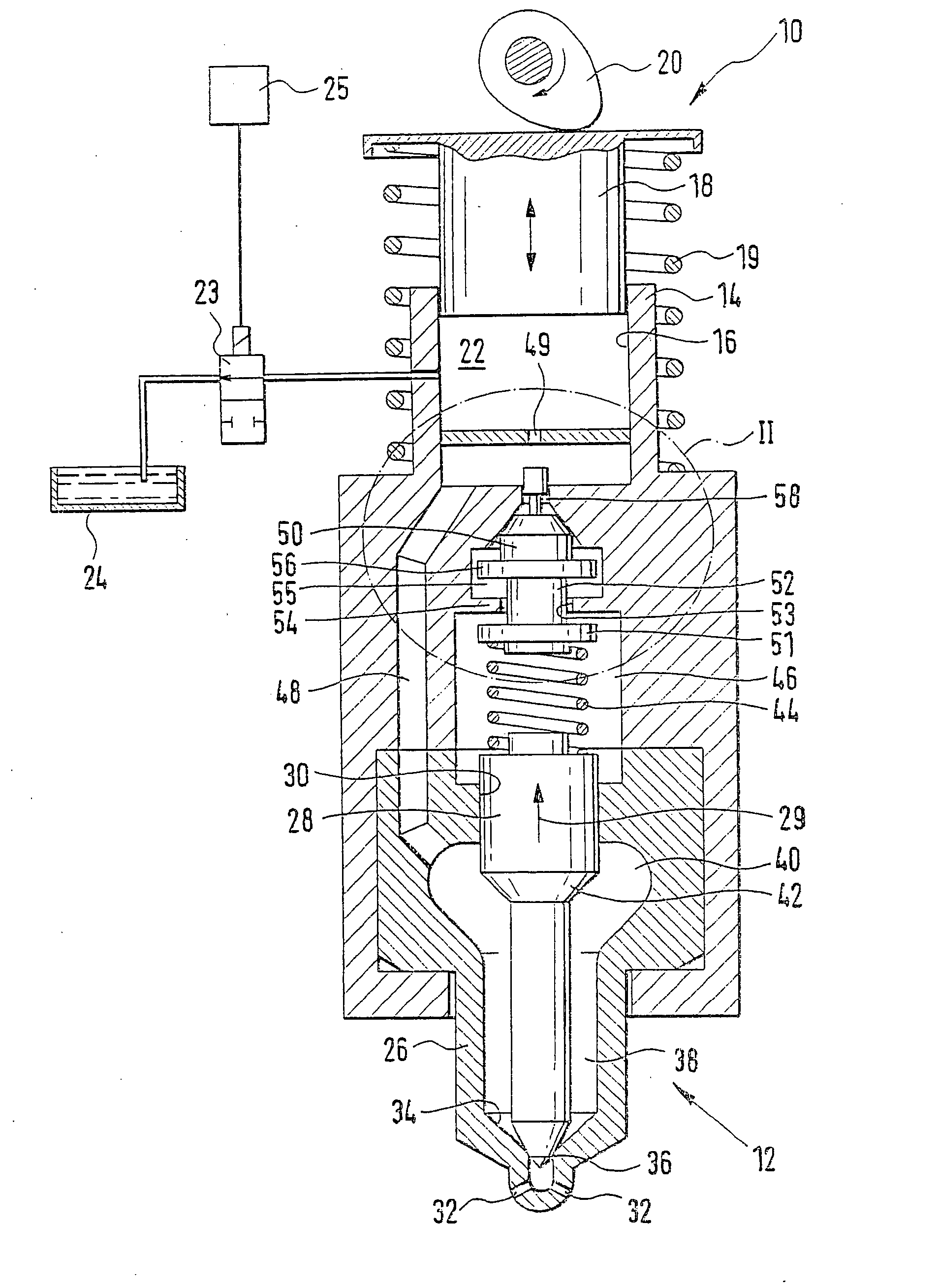
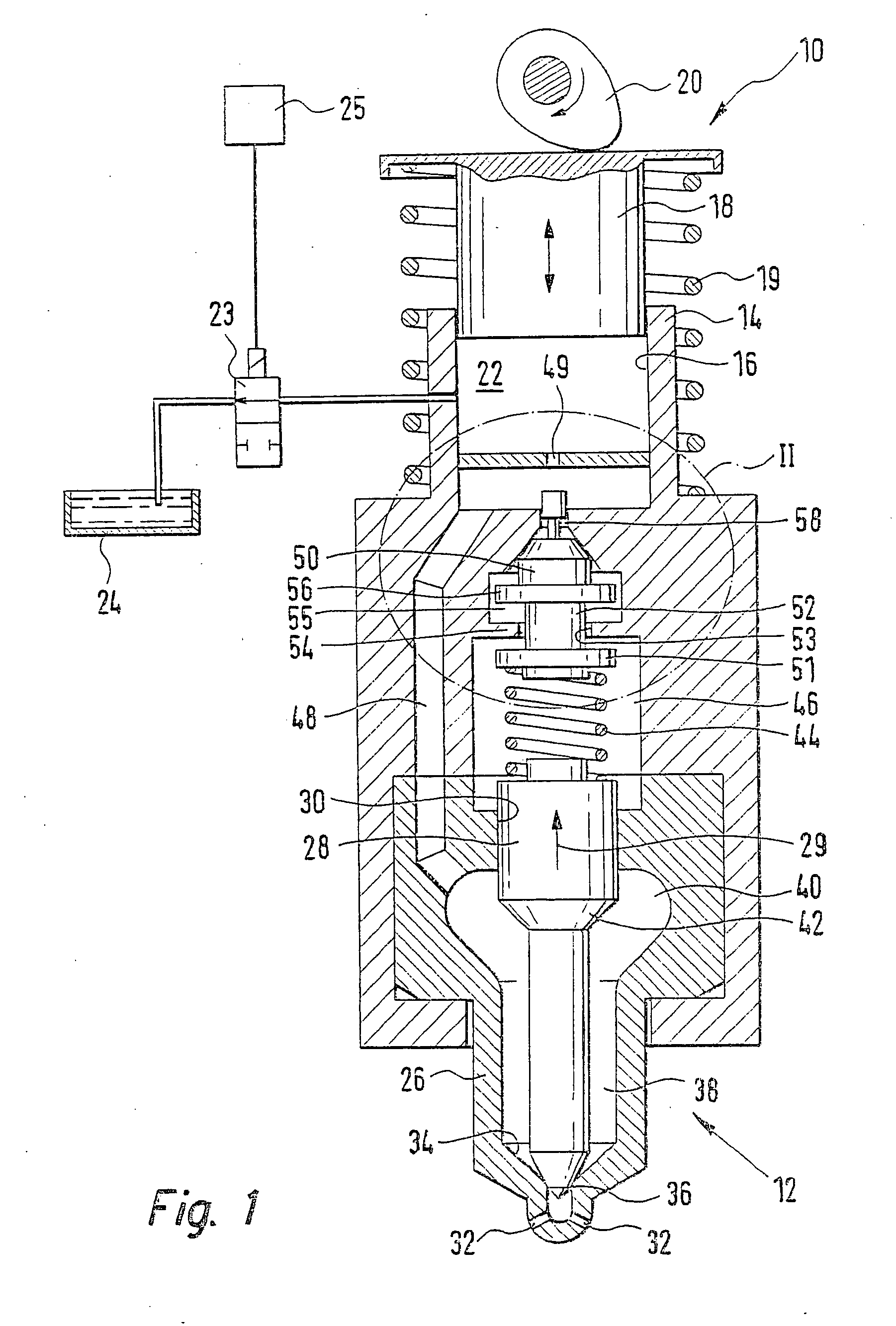
[0006] In FIGS. 1-5, a fuel injection system for an internal combustion engine 10 of a motor vehicle is shown. The engine has one or more cylinders, and for each cylinder there is one fuel injection system, with a high-pressure fuel pump 10 and a fuel injection valve 12. The high-pressure fuel pump 10 and the fuel injection valve 12 are combined into a so-called unit fuel injector. The high-pressure fuel pump 10 has a pump body 14, in which a pump piston 18 is guided tightly in a cylinder 16; the pump piston is driven in a stroke motion by a cam 20 of a camshaft of the engine, counter to the force of a restoring spring 19. In the cylinder 16, the pump piston 18 defines a pump work chamber 22, in which fuel is compressed at high pressure in the pumping stroke of the pump piston 18. In the intake stroke of the pump piston 18, fuel from a fuel tank 24 is delivered to the pump work chamber, for instance by means of a feed pump. The pump work chamber 22 has a communication with a relief ...


PUM


Abstract

The fuel injection system has a high-pressure fuel pump (10) and a fuel injection valve (12) for a cylinder of the engine. The high-pressure fuel pump (10) has a pump work chamber (22), and the fuel injection valve (12) has an injection valve member (28) by which at least one injection opening (32) is controlled and which is movable in an opening direction (29) counter to the force of a closing spring (44); the closing spring (44) is braced on one end on the injection valve member (28) and on the other end on a displaceable storage piston (50) that is acted upon, on its side remote from the closing spring (44), by the pressure prevailing in the pump work chamber (22). The storage piston (50) is movable into a storage chamber (55) counter to the force of the closing spring (44), and the deflection stroke motion of the storage piston (50) into the storage chamber (55) is limited by a stop (54). A shaft part (52), which has one shaft portion (74) of smaller cross section disposed in an outset position in a connecting bore (53) and one shaft portion (72) of larger cross section disposed outside the connecting bore (53) in the storage chamber (55), is movable with the storage piston (50), and upon the deflection stroke motion of the storage piston (50) into the storage chamber (55), the shaft portion (72) of larger cross section dips into the connecting bore (53).

Description

PRIOR ART[0001] The invention is based on a fuel injection system for an internal combustion engine as generically defined by the preamble to claim 1.[0002] One such fuel injection system is known from German Patent Disclosure DE 39 00 763 A1. This fuel injection system has a high-pressure fuel pump and a fuel injection valve for a cylinder of the engine. The high-pressure fuel pump has an engine-driven pump piston defining a pump work chamber, and a communication of the pump work chamber with a relief chamber is controlled by an electrically controlled valve. The fuel injection valve has an injection valve member, by which at least one injection opening is controlled, and which is movable in an opening direction, counter to the force of a closing spring disposed in a spring chamber, by the pressure prevailing in a pressure chamber that communicates with the pump work chamber. The closing spring is braced on one end at least indirectly on the injection valve member and on the other ...

Claims


Application Information

Patent Timeline
IPC IPC(8): F02M45/04F02M45/08F02M57/02F02M59/36F02M61/20F02M63/00
CPCF02M45/04F02M45/08F02M57/02F02M57/023F02M2200/505F02M61/205F02M2200/304F02M2200/40F02M59/366
Inventor DUPLAT, GERARDPOURRET, RAPHAELVOIJS, PETER
Owner ROBERT BOSCH GMBH
Why Eureka
Try Eureka