Slide unit mechanism

a technology of sliding mechanism and slide, which is applied in the direction of wing accessories, manufacturing tools, instruments, etc., can solve the problems of reducing the size of the torsion spring, limiting the size and arrangement of the operation button, and limiting the antenna arrangement in the monitor portion, so as to achieve the effect of reducing the size, reducing the size, and reducing the spring for

Active Publication Date: 2011-10-20
MITSUBISHI STEEL MFG CO LTD +1
View PDF3 Cites 3 Cited by
  • Summary
  • Abstract
  • Description
  • Claims
  • Application Information

AI Technical Summary

Benefits of technology

[0014]It is an object of the present invention to provide a thin slide mechanism that is to be incorporated in a portable electronic device and has sufficient spring force and high durability and also to provide a slide unit mechanism in which the internal slide structure viewable from the outside is reduced in size.

Problems solved by technology

Because a predetermined spring force is necessary to cause such device to slide, a specific limitation is placed on the possible reduction of the torsion spring in size.
Therefore, the size and arrangement of operation buttons are restricted.
As a result, possible arrangements of antenna in the monitor portion are limited in the portable electronic devices in which sliding is induced in the widthwise direction.
Consequently, this space acts as a technical barrier to thickness reduction in portable electronic devices incorporating a slide unit.

Method used


Image

  • Slide unit mechanism
  • Slide unit mechanism
  • Slide unit mechanism

Examples


embodiment 1

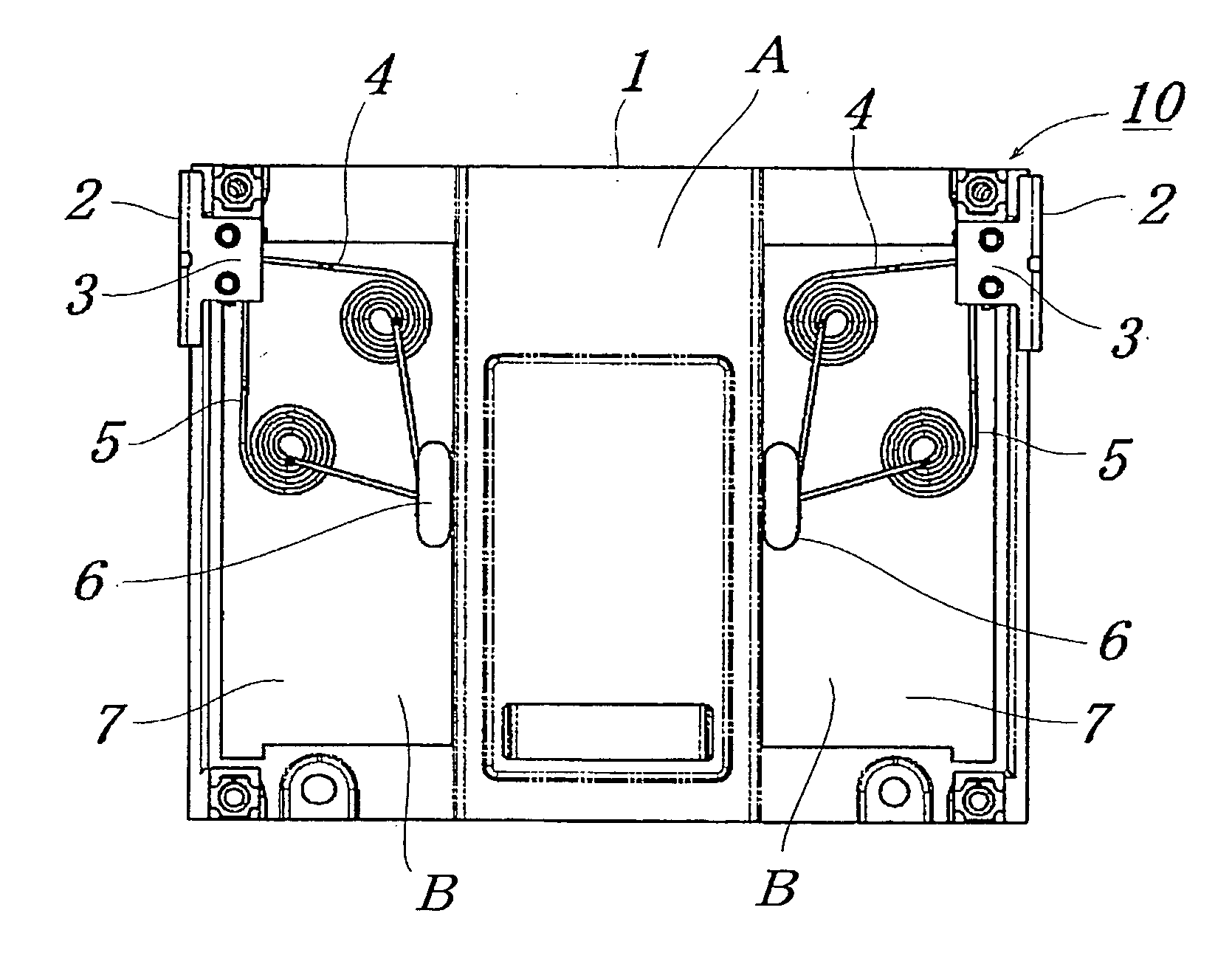
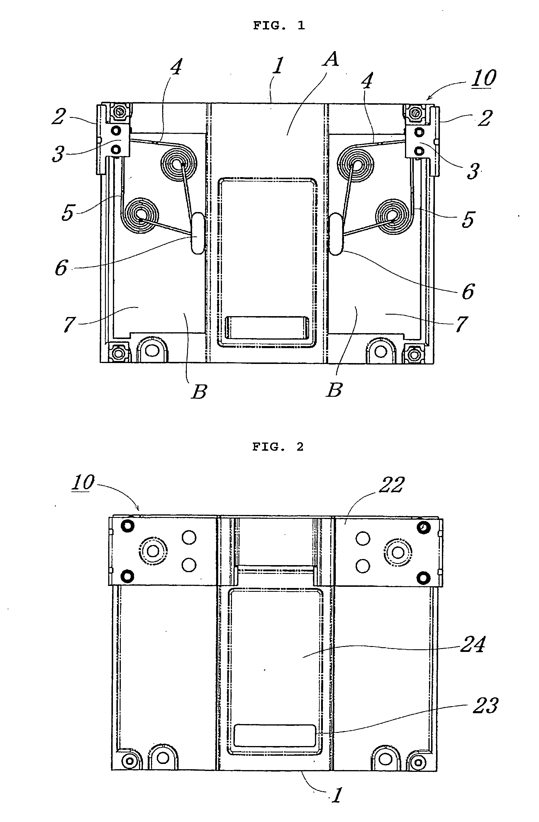
[0039]FIG. 1 and FIG. 2 are plan views illustrating a slide unit mechanism according to Embodiment 1. FIG. 1 and FIG. 2 show the structure of the slide unit mechanism 10 in which a housing (not shown in the figure) is closed. FIG. 1 is a plan view illustrating the slide unit mechanism according to Embodiment 1 that is viewed from the rear side, and FIG. 2 is a plan view showing the configuration on the front side.

[0040]As shown in FIG. 1, a plate 1 of a quadrangular shape in the plane view that is shown in FIG. 1 has a protruding portion A formed in the sliding direction in the center of the rear surface. Receding portions B are located at both sides of the protruding portion A.

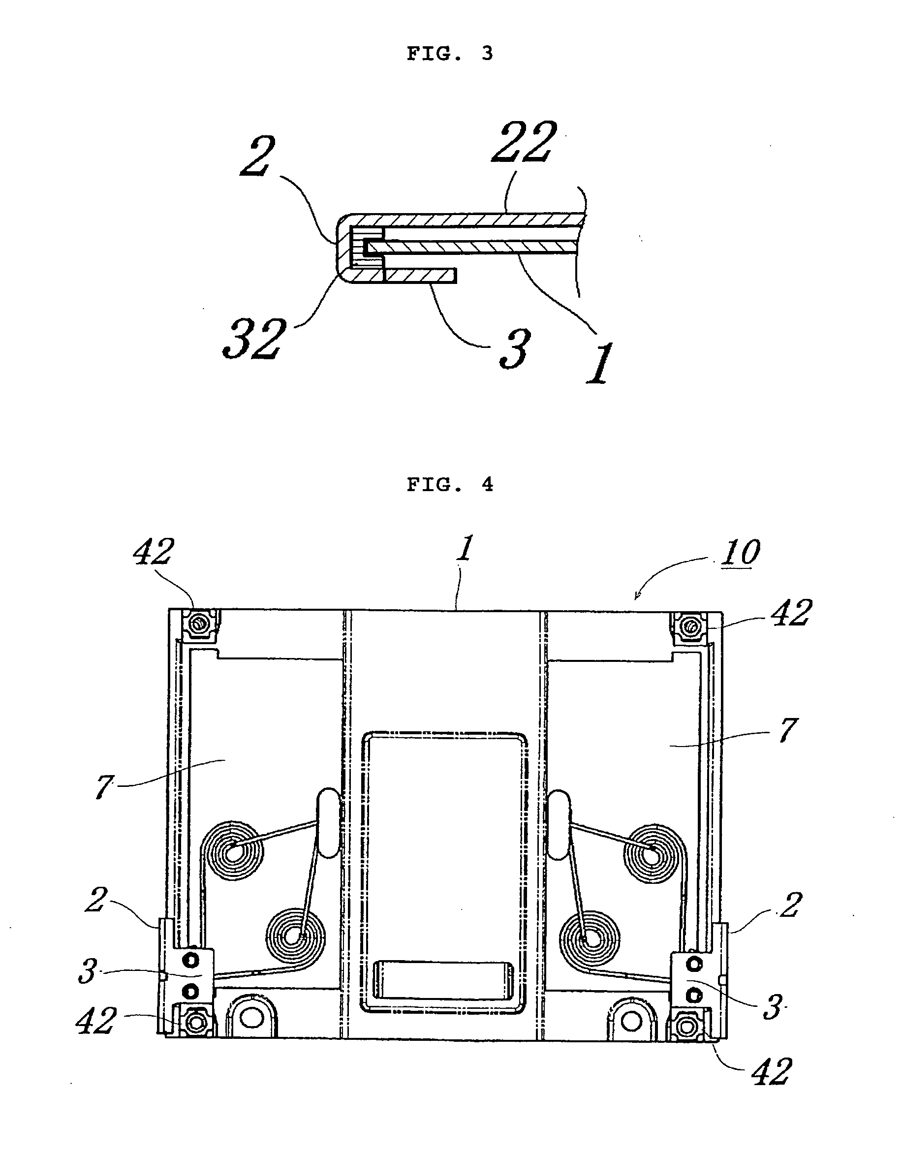
[0041]Two sliding members 2 are joined to both ends of the plate 1. Further, as shown in FIG. 2, these two sliding members 2 are integrally linked to the front side of the plate 1 by a linking member 22. The linking member 22 is formed to have a width equal to the longitudinal width of the sliding member 2 in...

embodiment 2

[0057]FIG. 6 and FIG. 7 are perspective drawings illustrating an example of a thin portable electronic device incorporating the slide unit mechanism 10 according to Embodiment 1. FIG. 6 shows the state in which the slide unit is closed, and FIG. 7 shows the state in which the slide unit is open. Components identical to those shown in FIG. 1 to FIG. 4 are assigned with same reference numerals.

[0058]As shown in FIG. 6, in a portable electronic device 60 according to the present embodiment, the plate 1 of the slide unit mechanism 10 is fixedly attached to a first housing (monitor portion) 61. The linking member 22 of the slide unit mechanism 10 is fixedly attached to a second housing (main body section) 62. The slide unit mechanism 10 is incorporated so as to be capable of sliding in the lateral direction of the housing.

[0059]In the portable electronic device 60 according to the present embodiment, the monitor portion 61 has a width of 114 mm, a length of 54.5 mm, and a height of 6.6 m...


PUM


Abstract

The present invention relates to a thin slide mechanism that can be incorporated in a portable electronic device. A slide unit mechanism having: a plate 1 of a quadrangular shape in a plane view in which a protruding portion A is formed in a sliding direction in the center of the rear surface and receding portions B are formed in two locations respectively to the left and to the right of the protruding portion; two sliding members 2 slidably joined to both ends of the plate; and a linking member 22 that integrally links the two sliding members on the front surface side of the plate and has a width substantially equal to or less than a longitudinal width of the sliding member in the sliding direction, wherein the entire portion or a part of the rear surface portion of the folded sliding member, when folded to the rear surface, is extended to serve as stopper portions 3, a torsion spring is arranged in each of the left and right receding portions of the plate, one end of each torsion spring is locked to the substantially central portion, in the sliding direction, of the side surface of the protruding portion formed on the plate, the other end of each torsion spring is locked to the stopper portions of the sliding members, connection members for connection to a housing are formed at the approximately four corners of the plate, and sliding ends are formed when the connection members and the stopper portions of the sliding members abut on each other.

Description

BACKGROUND OF THE INVENTION[0001]1. Field of the Invention[0002]The present invention relates to a thin slide mechanism that can be incorporated in a portable electronic device such as a cellular phone, a PHS, and a PDA, and more particularly to a slide unit mechanism having high durability and reduced surface area of the internal slide structure that can be viewed from the outside.[0003]2. Description of the Related Art[0004]The so-called slide-type portable electronic device in which a main body portion and a monitor portion are divided into two layers of an upper layer portion and a lower layer portion and an operation portion located on the inner side of the lower layer portion is exposed by sliding the upper layer portion are presently well known.[0005]In the conventional slide-type portable electronic device, a slide device is used in which one end of a torsion spring is fixedly attached to a first housing serving as the monitor portion and the other end is fixedly attached to...

Claims


Application Information

Patent Timeline
Patent Type & Authority Applications(United States)
IPC IPC(8): H04M1/02
CPCG06F1/1624Y10T16/545H04M1/0237H04B1/38H04M1/02
Inventor MITSUI, YASUHIROSHIMOMURA, YOSHINORI
Owner MITSUBISHI STEEL MFG CO LTD
Why Eureka
Try Eureka