Automobile seat slide rail mechanism
A car seat slide rail and slide rail technology, which is applied in the direction of vehicle seats, movable seats, vehicle parts, etc., can solve the problems of mutual friction and collision, abnormal noise, etc., and achieve small friction and collision force, small force, and unlocking and locking action flexible effect
- Summary
- Abstract
- Description
- Claims
- Application Information
AI Technical Summary
Problems solved by technology
Method used
Image
Examples
Embodiment 1
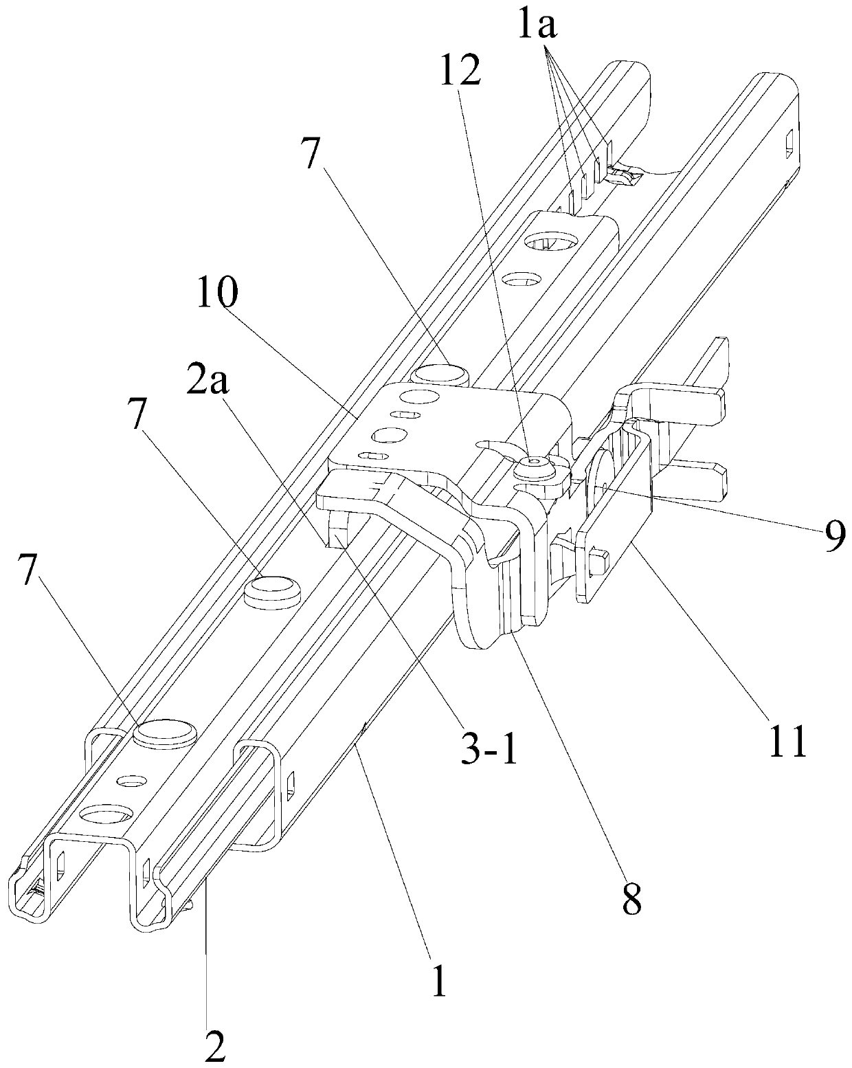
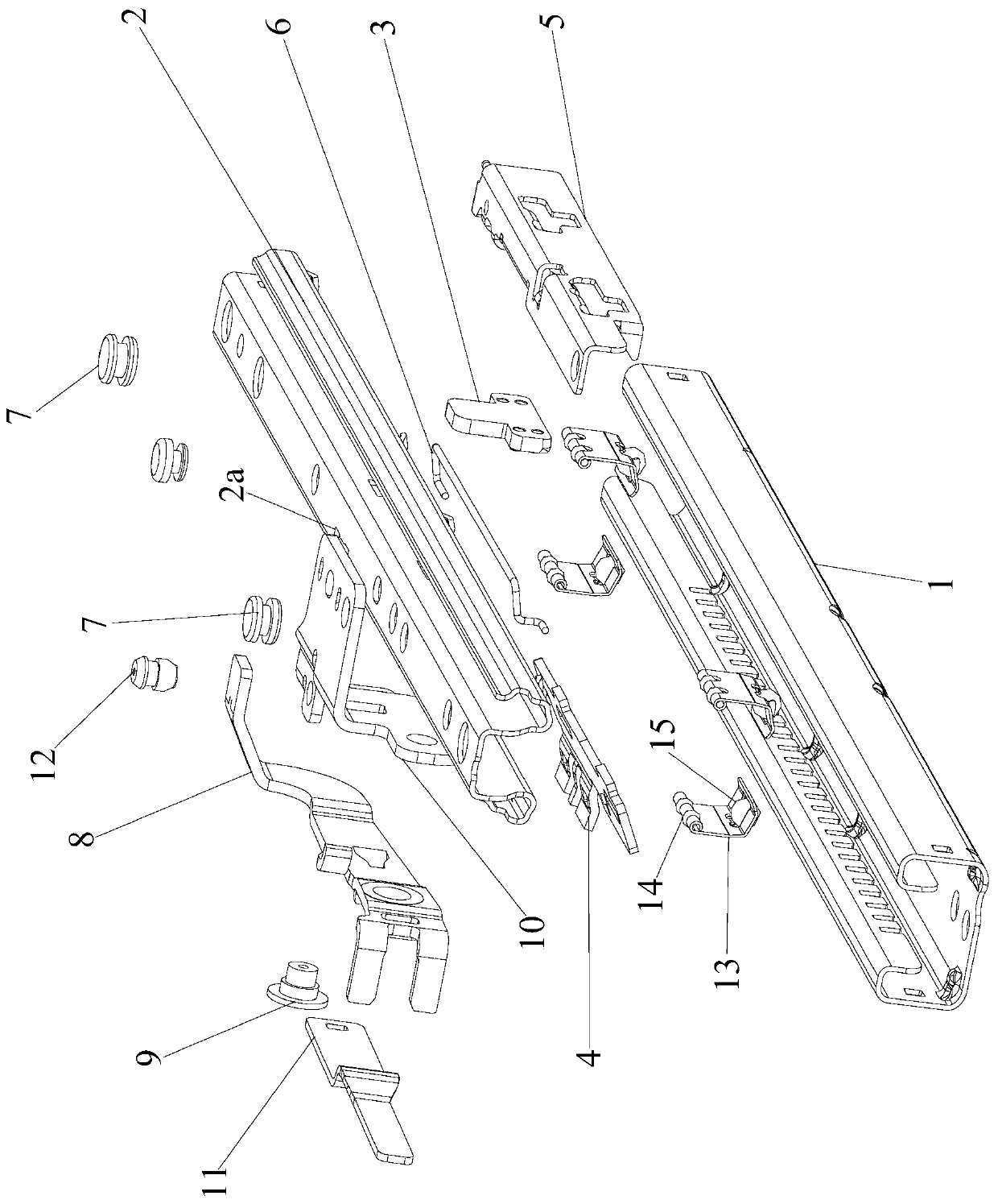
[0059] Such as Figure 1 to Figure 8 As shown, the present invention discloses a car seat slide rail mechanism, including a lower slide rail 1, an upper slide rail 2, a locking and unlocking assembly and an operating assembly. The operation component controls the car seat slide rail mechanism to enter the locked state or the unlocked state through the locking and unlocking component, and the lower rail 1 and the upper rail 2 cannot slide relative to each other in the locked state. Can slide relatively in the unlocked state;
[0060] The side of the down rail 1 is provided with a plurality of locking grooves 1a arranged at intervals along the extending direction of the down rail 1, and the locking grooves 1a are notches with openings facing downward; for example: figure 1 In the shown embodiment, the locking groove 1a is arranged on the left side of the sliding rail 1, but the present invention does not rule out that the locking groove 1a is arranged on the right side of the s...
Embodiment approach
[0074] The top surface of the lock claw 4 is provided with a guide slot 4a and a limit claw 4-3; the lock claw bracket 5 is also provided with a guide pin 5-1 and a limit member 5-2;
[0075] The guide pin 5-1 is inserted into the guide slot 4a, so that: when the lock claw 4 rotates downward or upward around the lower edge 5a1 of the lock claw bracket support hole 5a, the lock claw 4 Rotate along the guide pin 5-1;
[0076] The limiting claw 4-3 extends into the limiting hole 5-2a of the limiting member 5-2, so that: when the car seat slide rail mechanism is in the unlocked state, the limiting member 5 -2 restricting the downward movement of the limiting claw 4-3, limiting the locking claw 4 to stop rotating downward around the lower edge 5a1 of the supporting hole 5a of the locking claw bracket;
[0077] When the car seat slide rail mechanism is in the locked state, the control handle lower part 3-2 of the control handle 3 abuts against the inner side wall of the top surface...
Embodiment 3
[0080] On the basis of the above-mentioned embodiment two, the present embodiment three also adopts the following preferred implementation modes:
[0081] The connection mode between the back-moving spring 6 and the locking claw 4 and the locking claw bracket 5 is as follows:
[0082] The return spring 6 is a torsion spring composed of a first hook 6-1, a straight section 6-2, a curved section 6-3 and a second hook 6-4;
[0083] The top surface of described locking pawl 4 is also provided with back-moving spring installation groove 4b; Described locking pawl support 5 is also provided with hook 5-3 and back-moving spring supporting part 5-4;
[0084] The first hook 6-1 is hooked to the hook 5-3, the straight section 6-2 is supported on the return spring supporting member 5-4, and the second hook 6-4 snapped into the return spring installation groove 4b.
[0085] Therefore, the present invention can make the structure of the locking and unlocking assembly more compact, and on...
PUM
 Abstract
Description
Claims
Application Information
 - R&D
- Intellectual Property
- Life Sciences
- Materials
- Tech Scout
- Unparalleled Data Quality
- Higher Quality Content
- 60% Fewer Hallucinations
Browse by: Latest US Patents, China's latest patents, Technical Efficacy Thesaurus, Application Domain, Technology Topic, Popular Technical Reports.
© 2025 PatSnap. All rights reserved.Legal|Privacy policy|Modern Slavery Act Transparency Statement|Sitemap|About US| Contact US: help@patsnap.com


