
Valve devices for internal combustion engines

A technology for valve devices and internal combustion engines, which is applied to valve devices, mechanical equipment, engine components, etc., can solve the problems of insufficient sealing and valve adjustability due to thermal characteristics, and reduce the number of components, improve service life, and simplify Assembly effect

Active Publication Date: 2017-12-01
PIERBURG GMBH & CO KG NEUSS
View PDF2 Cites 0 Cited by
  • Summary
  • Abstract
  • Description
  • Claims
  • Application Information

AI Technical Summary

Problems solved by technology

[0006] The corresponding disadvantage of the known design is that it does not provide sufficient sealing when the thermal properties change and at the same time it does not provide an adjustability of the valve without fear of the valve being stuck.

Method used


Image

  • Valve devices for internal combustion engines
  • Valve devices for internal combustion engines

Examples


Embodiment Construction

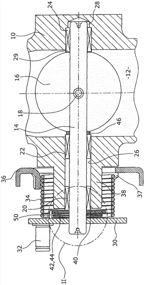
[0022] The flap arrangement according to the invention consists of a flow housing 10 in which a flow channel 12 is formed, for example through which exhaust gas can flow.

[0023] The flow channel 12 is divided in half by an adjusting shaft 14 in cross section, to which a valve body 16 is fastened by means of screws 18 . The adjusting shaft 14 is mounted in the flow housing 10 via three bushings 20 , 22 , 24 , of which the first two bushings 20 , 22 are seated in a through-opening 26 through which the adjusting shaft 14 passes from the The flow housing 10 protrudes outwards, and a third bushing 24 is seated on the side opposite the bore 26 in a blind hole 28 formed in the flow housing 10 , wherein the third bushing 24 has an axial direction The ends protrude into the flow channel 12 . Correspondingly, there are bearings on both sides of the adjusting shaft 14 on the side opposite to the central axis of the flow housing 10 .

[0024] On the outwardly protruding end of the adj...


PUM


Abstract

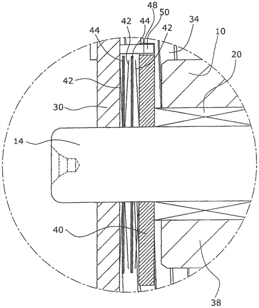
A valve arrangement for an internal combustion engine is known, which has a flow housing (10), in which a flow channel (12), an adjusting shaft (14), a valve body (16) are formed, The valve body (16) is arranged in the hole (26) in the flow housing (10) on the adjustment shaft (14) in the flow passage (12), and the adjustment shaft (14) passes through the The hole (26) protrudes outwards, the first bushing (20), the adjustment shaft (14) is supported in the first bushing (20) and the first bushing (20) is placed on the bore (26), wherein the axial end of the sleeve (20) protrudes beyond the end of said bore (26), and a seal which radially surrounds said adjustment shaft (14) and There is at least one spring element. In order to obtain a better seal even in the event of thermal expansion, it is provided here that the seal has a first disc (30) and a second disc (40), in which the first disc ( 30) and the second disk (40) at least one disk spring (42) is arranged as a spring, wherein the first disk (30) is fastened to the adjustment shaft (14) and serves as an abutment for said at least one disc spring (42), said at least one disc spring (42) being preloaded against said second disc (40) so that said A second disc (40) is spring loaded against an axial end of said first bushing (20) protruding from said bore (26).

Description

technical field [0001] The invention relates to a valve arrangement for an internal combustion engine, which has a flow housing, in which a flow channel is formed, an adjusting shaft, a valve body, which is arranged in the flow channel and on the adjusting shaft Upper, a hole in the flow housing through which the adjustment shaft protrudes outwards, a first sleeve in which the adjustment shaft is supported and the first sleeve is placed on the The bore, wherein the axial end of the bushing protrudes beyond the end of the bore, and a seal radially surrounding the adjustment shaft and having at least one spring member. Background technique [0002] Such flap arrangements are used, for example, as exhaust gas choke flaps or exhaust gas recirculation valves in the exhaust gas line of internal combustion engines. Exhaust gases contain harmful substances, which must not escape to the outside, so that a reliable seal must be ensured along the shaft, which projects outwards in the ...

Claims


Application Information

Patent Timeline
IPC IPC(8): F02D9/10F02D9/04F16K1/226F16K1/22
CPCF02D9/106F02D9/04F16K1/226F16K1/2268
Inventor M.埃弗斯
Owner PIERBURG GMBH & CO KG NEUSS
Learn More