High reliability zero insertion force connector and assembly

Active Publication Date: 2019-07-16
MIRACO
View PDF8 Cites 3 Cited by
  • Summary
  • Abstract
  • Description
  • Claims
  • Application Information

AI Technical Summary

Benefits of technology

[0021]Finally, the connector assembly includes at least one latch disposed on either side of the housing. Each latch includes a first end disposed toward the front section of the housing, a second end disposed toward the back section of the housing, and a flexing section disposed between the first and second ends. As discussed above, each latch includes a protrusion that protrudes in toward the housing and mates with the open and closed position detents of the actuator. The protrusions are included on the flexing section of the latch. Indeed it is the flexibility of the flexing section that allows the protrusion to move between the open and closed position detents. The latches preferably include an actuator stop at the second end of the latches. The actuator stops are essentially lips extending in toward the housing that do not allow the actuator to come out of the housing after assembly. In preferred embodiments, the flexing section provides sufficient spring force to automatically return the actuator to the closed position, rather than requiring the manual repositioning of the handle of the rotator.
[0022]The latches preferably also include a housing retention tab and a latch foot disposed at the first end of the latches. In embodiments that include a housing retention tab, the housing also includes a latch retention pocket. In these emb

Problems solved by technology

With such a small deflection range, and when the FPC or FFC are at the minimum thickness tolerance, the connection may not provide the minimum contact force.
As a result, these connectors are more prone do discontinuity in environments where the connector will be subject to shock and vibration conditions which may induce motion and cause the contact to deflect.
Any movement or disengagement of the a

Method used


Image

  • High reliability zero insertion force connector and assembly
  • High reliability zero insertion force connector and assembly
  • High reliability zero insertion force connector and assembly

Examples


Embodiment Construction

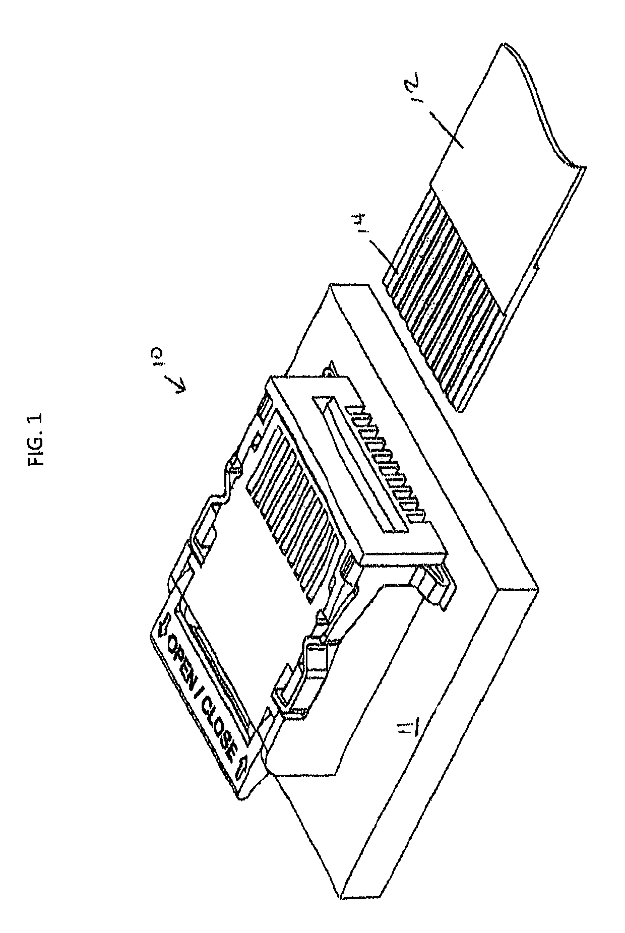
[0077]Referring first to FIG. 1 a perspective view of the preferred embodiment of the connector assembly 10 of the present invention mounted on a PCB 11 with an FPC or FFC 12 with conductors 14 to be inserted is provided. As used herein, FPC and FFC are collectively referred to as “flat male connectors.” It is understood that PCB 11 may be replaced by an FPC and that the terms PCB and FPC are collectively referred to herein as “printed circuit.”

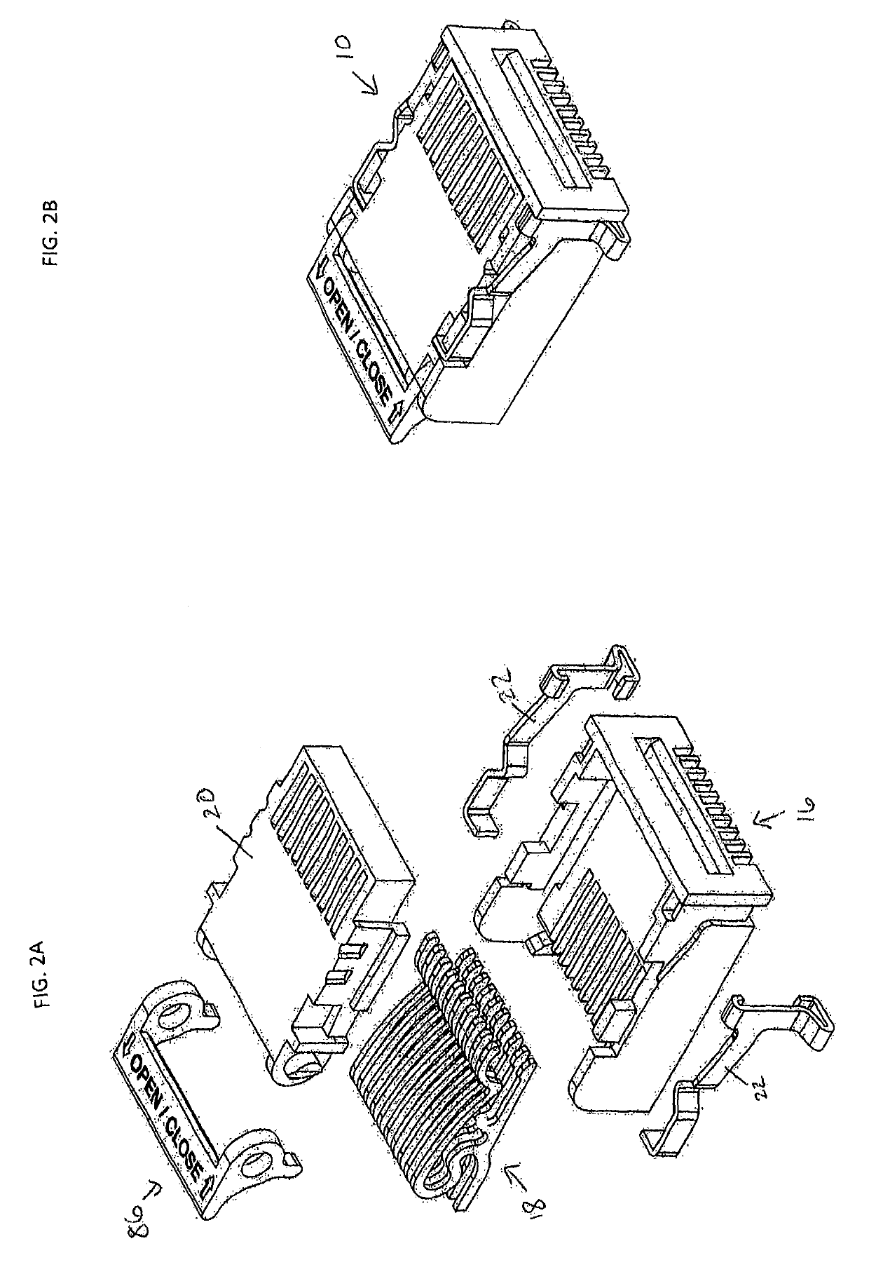
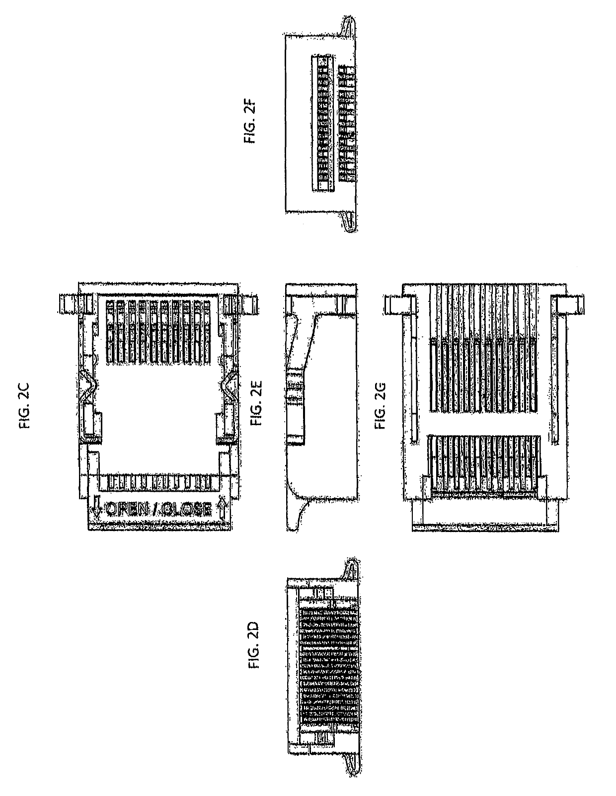
[0078]Now referring to FIG. 2A, a perspective view of the connector assembly 10 with the components separated for illustrative purposes is provided. Connector assembly 10 includes housing 16, contacts 18, actuator 20 with rotator 86, and latches 22. Each of these components will be described in more detail below. Now referring to FIGS. 2B-2F, perspective, top down, back, right side, front, and bottom up views of the connector assembly, respectively, are provided. Although a latch 22 is shown on either side of housing 16, it is understood that...


PUM


Abstract

This invention is a means for interconnecting a Flexible Printed Circuit (FPC) or Flat Flexible Cable (FFC) with a Printed Circuit Board (PCB) using a Zero Insertion Force (ZIF) style interconnection system. It features a high reliability contact structure providing a Normally Closed (NC) contact configuration which is always engaged unless deactivated by means of a movable actuator.

Description

CLAIM OF PRIORITY[0001]This application claims the benefit of priority of U.S. Provisional Patent Application Ser. No. 62 / 537,983, filed on Jul. 28, 2017.FIELD OF THE INVENTION[0002]The present invention relates to the field of multiple-conductor Flexible Printed Circuits (FPCs), Flat Flexible Cables (FFCs), and Zero Insertion Force (ZIF) style electrical connectors used for interconnecting said circuits with other electrical devices.BACKGROUND[0003]Today's market for mobile electronics has driven connector manufacturers to push the limits of miniaturization to produce smaller and smaller connectors for FPC and FFC. These miniaturized connectors use thinner plastics and smaller contacts and achieve lower contact forces. As a result, a segment of the market has been left out which is those manufacturers whose product's primary requirement is ruggedness and reliability. These products are generally in the military, aviation, medical, and automotive markets.[0004]ZIF style interconnect...

Claims


Application Information

Patent Timeline
IPC IPC(8): H01R12/88H01R13/11H01R13/03H01R12/79
CPCH01R12/88H01R13/112H01R13/03H01R12/79H01R12/89
Inventor BULMER, DOUGLASROBERTS, JONATHAN
Owner MIRACO
Why Eureka
Try Eureka