Medical Tubing Stabilization Device

a technology for stabilizing devices and medical tubing, which is applied in the direction of breathing protection, infusion needles, other medical devices, etc., can solve the problems of obstructing access, affecting the operation of surgeons,

Active Publication Date: 2011-10-20
IMAGIDENT
View PDF23 Cites 5 Cited by
  • Summary
  • Abstract
  • Description
  • Claims
  • Application Information

AI Technical Summary

Benefits of technology

Standard nasotracheal tube diameters vary from 4.5 mm to 8.5 mm depending on the size of the patient. In the preferred embodiment, the superior central depression would have a depth of half to twice the diameter of the tubing to be supported. A piece of operating room tape extending from the headband across the tubing resting in the foam block and attaching to the headband again on the other side provides maximum compression of the foam block resulting in a secure attachment. In another embodiment the tape may be substituted by a Velcro type connecting surface. In another embodiment the tape may have an elastic property to securely position the tube in the channel. In another embodiment a friction fit may be used to position the tubing securely in the channel.
The present invention enables the surgeon to be unencumbered with nasotracheal tubing whilst performing surgery on the head, neck, and oral cavity. Further, the tubing is able to be repositioned or removed.

Problems solved by technology

During surgery of the head and neck existing methods of securing nasotracheal tubing can be a hindrance to the surgeon, either obstructing access to or blocking a clear view of the surgical area.
This method results in a number of problems.
It is difficult to readjust placement of the tape, difficult to remove the tape, and the patient's hair is pulled out when the tape is removed.
This method does not provide adequate support to stabilize the tubing if it is inadvertently contacted during surgery, and may result in an accidental extubation.
Another method involves custom cutting a piece of foam, however this is time consuming and non-standardized.
The raw edges created by the cuts also impose a hazard of microscopic flecks of foam being dispersed and potentially contaminating the surgical area.
Accordingly, prior to the development of the present invention, positioning the nasotracheal tubing securely away from the surgical area has been laborious and lacking in predictable stability.
Most importantly, other methods do not adequately prevent accidental extubation.

Method used


Image

  • Medical Tubing Stabilization Device
  • Medical Tubing Stabilization Device
  • Medical Tubing Stabilization Device

Examples


Embodiment Construction

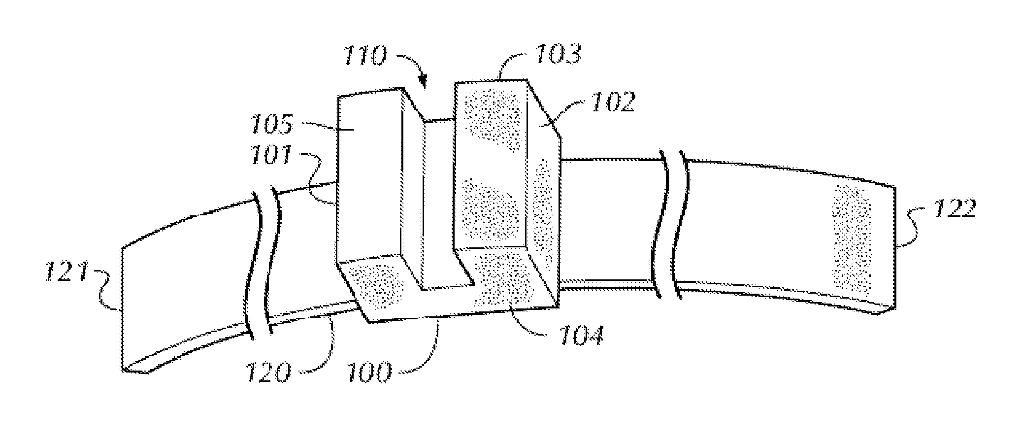
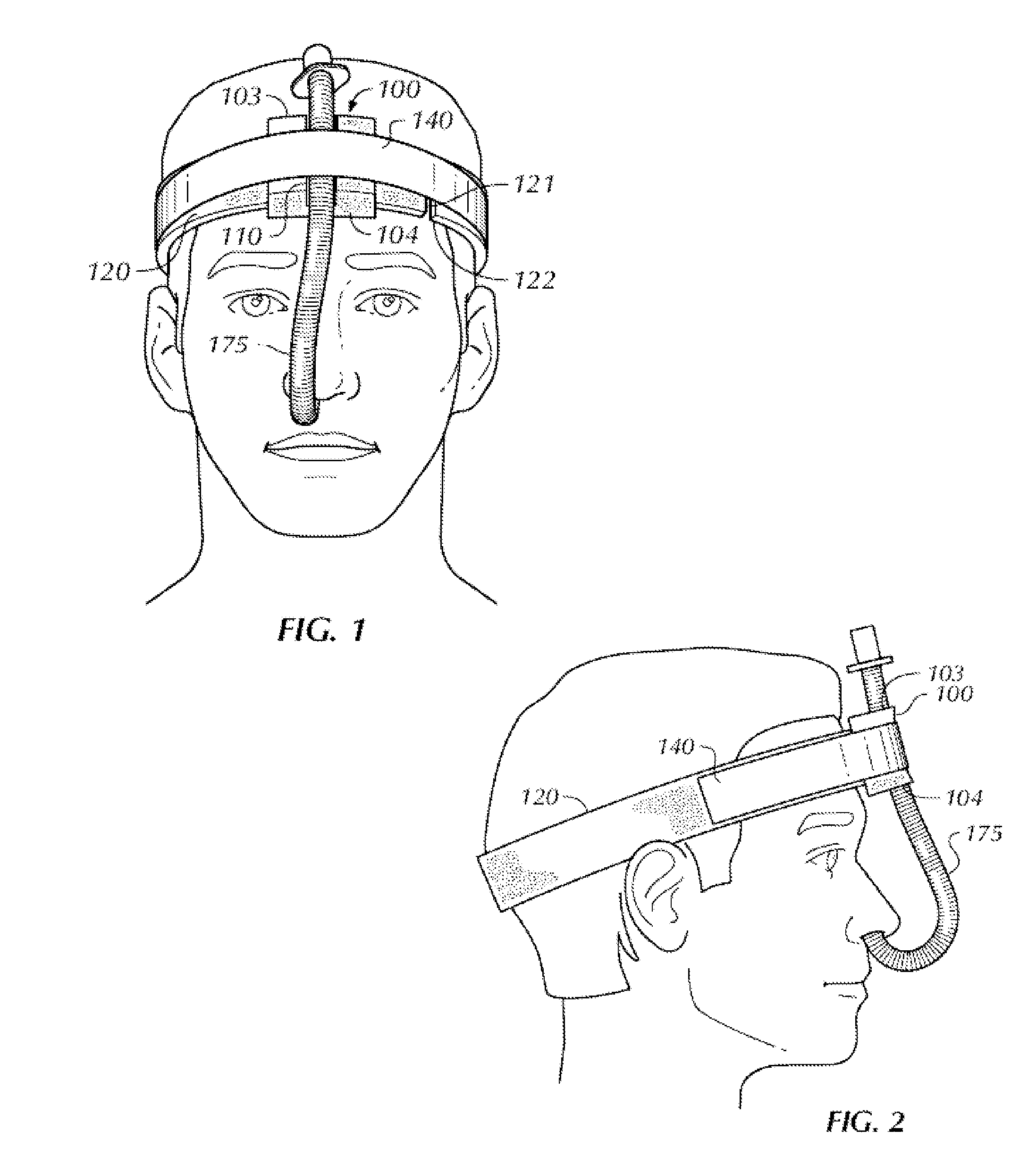
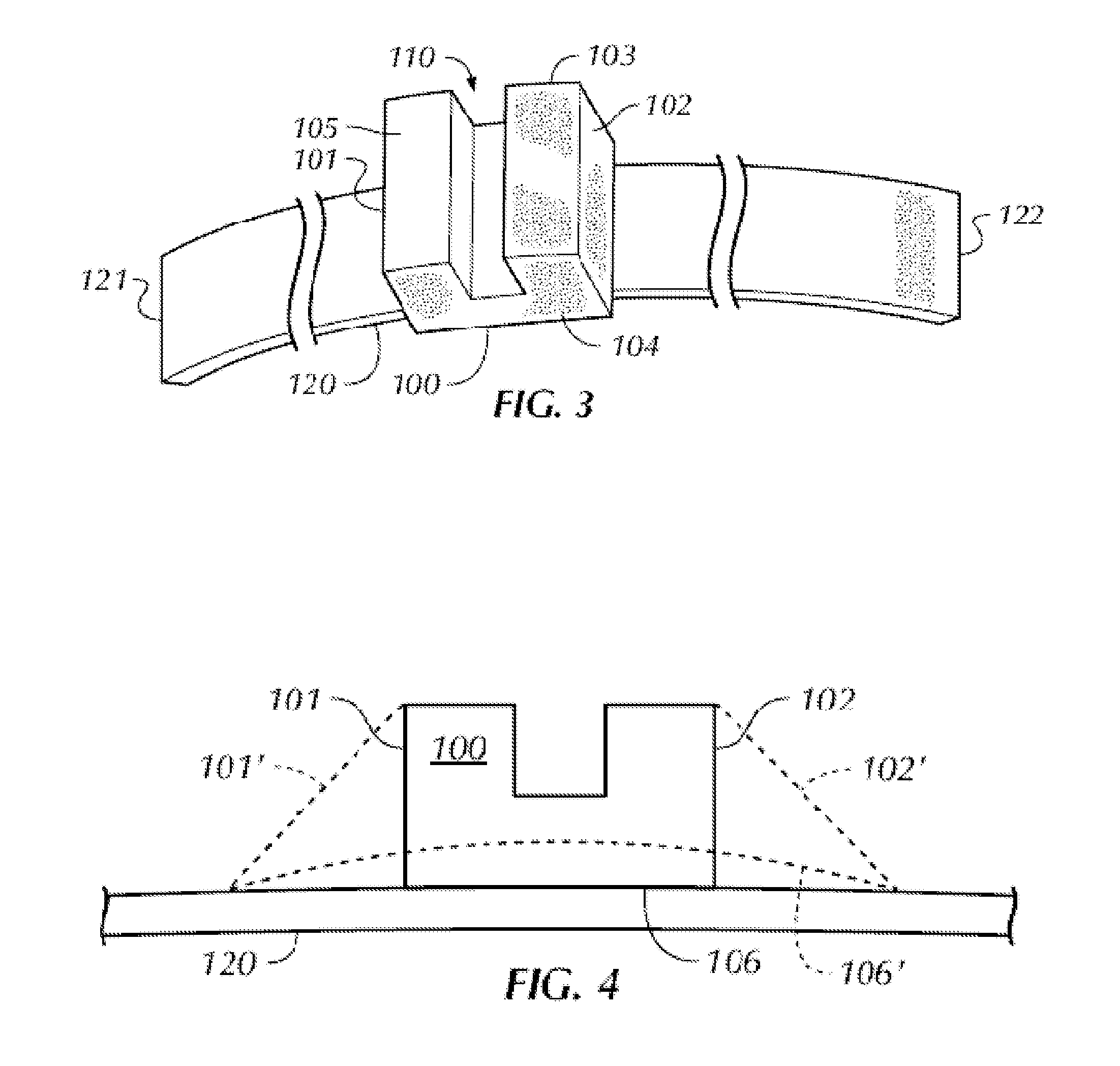
In accordance with the invention the foregoing advantages have been achieved through the present nasotracheal tubing stabilizing device. The present invention includes a substantially U-shaped compressible foam block. The block being comprised of opposing, substantially parallel superior and inferior surfaces and opposing substantially parallel anterior and posterior sides substantially perpendicular to the superior and inferior surfaces. The block further being comprised of opposing left and right sides and having a superior central depression, or channel, along its superior surface extending from the anterior to posterior surfaces, said channel having a depth of less than half of the length of the sides of the block. The length being determined as the distance from the anterior to the posterior surfaces.

Standard nasotracheal tube diameters vary from 4.5 mm to 8.5 mm depending on the size of the patient. In the preferred embodiment, the superior central depression would have a dept...


PUM


Abstract

A medical stabilization device that directs medical tubing onto a compressible foam block where it is attached and stabilized to the patient's body allowing it to be secured against excessive movement, tube dislodgement and positioned in a time efficient manner to prevent obstruction of patient treatment.

Description

BACKGROUND OF THE INVENTIONDuring surgery of the head and neck existing methods of securing nasotracheal tubing can be a hindrance to the surgeon, either obstructing access to or blocking a clear view of the surgical area. One of the methods used to direct the nasotracheal tubing away from the surgical area is to secure the tubing to the patient's head using operating room tape. This method results in a number of problems. It is difficult to readjust placement of the tape, difficult to remove the tape, and the patient's hair is pulled out when the tape is removed.Another method is to place a towel between the nasotracheal tubing and the forehead. This method does not provide adequate support to stabilize the tubing if it is inadvertently contacted during surgery, and may result in an accidental extubation.Another method involves custom cutting a piece of foam, however this is time consuming and non-standardized. The performance of this method is variable depending on the nature of t...

Claims


Application Information

Patent Timeline
Patent Type & Authority Applications(United States)
IPC IPC(8): A61M39/00A61M16/00
CPCA61M16/0461A61M16/0488A61M16/0683A61M25/02A61M2209/088A61M2025/0213A61M2025/024A61M2025/026A61M2039/087A61M2025/0206
Inventor JUNDT, CHERYL LEWIS
Owner IMAGIDENT
Why Eureka
Try Eureka