Multi-band antenna

Inactive Publication Date: 2011-10-20
QUANTA COMPUTER INC
View PDF9 Cites 3 Cited by
  • Summary
  • Abstract
  • Description
  • Claims
  • Application Information

AI Technical Summary

Benefits of technology

[0007]Therefore, an object of the present invention is to provide an ante

Problems solved by technology

However, the above-mentioned schemes compro

Method used


Image

  • Multi-band antenna
  • Multi-band antenna
  • Multi-band antenna

Examples


Example

[0019]Before the present invention is described in greater detail, it should be noted that like elements are denoted by the same reference numerals throughout the disclosure.

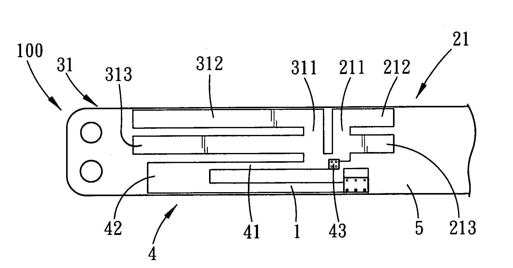
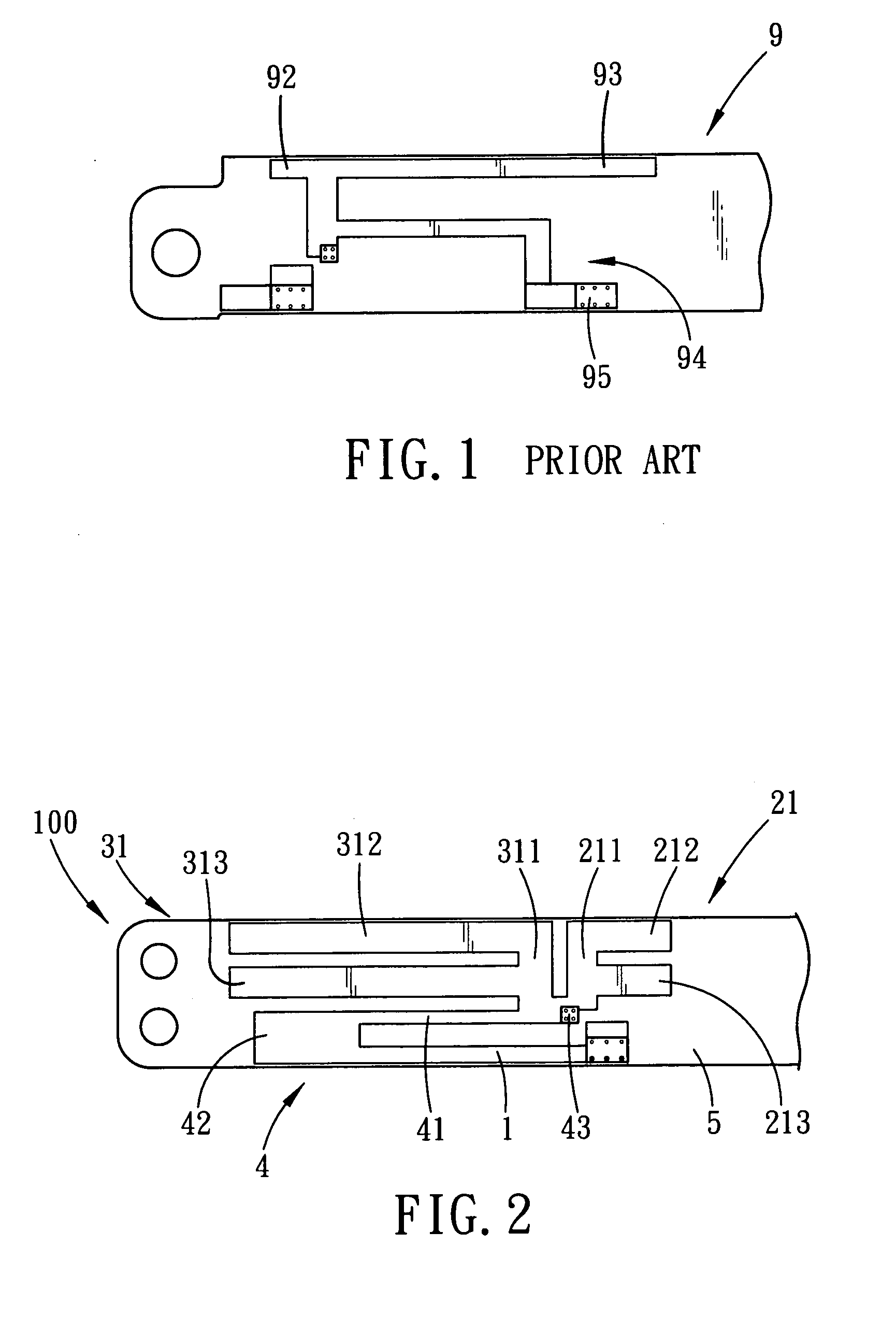
[0020]Referring to FIG. 2, the first preferred embodiment of a multi-band antenna 100 according to the present invention is adapted for disposing on a substrate 5, and includes an elongated grounding element 1, a connecting element 4, and first and second radiator elements 21, 31.

[0021]The grounding element 1 has opposite first and second ends. The connecting element 4 is substantially L-shaped, and includes an elongated first connecting section 41, and a second connecting section 42 that extends substantially perpendicular from the first end of the grounding element 1 and that connects the first connecting section 41 to the grounding element 1. The first connecting section 41 extends from the second connecting section 42 in a direction from the first end to the second end of the grounding element 1, and is subs...


PUM


Abstract

An antenna includes a grounding element, a connecting element, and first and second radiator elements. The connecting element includes an elongated first connecting section, and a second connecting section connecting the first connecting section to the grounding element. The first radiator element includes a first radiator section extending substantially perpendicular from one side of the first connecting section, and second and third radiator sections extending substantially perpendicular from one side of the first radiator section. The second radiator element includes a first radiator portion extending substantially perpendicular from the one side of the first connecting section, and second and third radiator portions extending substantially perpendicular from one side of the first radiator portion and extending in an opposite direction relative to the second and third radiator sections.

Description

CROSS-REFERENCE TO RELATED APPLICATION[0001]This application claims priority of Taiwanese Application No. 099112352, filed on Apr. 20, 2010.BACKGROUND OF THE INVENTION[0002]1. Field of the Invention[0003]The present invention relates to a multi-band antenna, more particularly to an antenna with peak gain suppression and a relatively high radiation efficiency.[0004]2. Description of the Related Art[0005]Referring to FIG. 1, a conventional dual resonance inverted-F antenna 9 includes a linear first radiator portion 92, a linear second radiator portion 93, a grounding portion 95, and a step-like connecting portion 94 connecting electrically the first and second radiator portions 92, 93 to the grounding portion 95. The first radiator portion 92 and the connecting portion 94 constitute a first radiator arm resonant in a first frequency band. The second radiator portion 93 and the connecting portion 94 constitute a second radiator arm resonant in a second frequency band that is lower than...

Claims


Application Information

Patent Timeline
IPC IPC(8): H01Q1/38H01Q5/10
CPCH01Q9/42H01Q1/2266
Inventor CHIU, CHIEH-PINGWENG, FENG-JENWU, HSIAO-WEIYEN, I-PING
Owner QUANTA COMPUTER INC
Why Eureka
Try Eureka