Antenna unit and electronic device

Active Publication Date: 2019-12-19
MURATA MFG CO LTD
View PDF0 Cites 0 Cited by
  • Summary
  • Abstract
  • Description
  • Claims
  • Application Information

AI Technical Summary

Benefits of technology

The patent describes a configuration where two coil antennas are placed on a metal body. The magnetic fluxes from each coil are directed at an intermediate position between the two conductive portions. This results in a hot spot at that position, where the magnetic fluxes are in phase with each other. This configuration can be used in electronic devices to create a more uniform magnetic field and improve performance.

Problems solved by technology

However, when the metal body is arranged in proximity to the antenna, it may be difficult to position the hot spot almost immediately above the metal body.

Method used


Image

  • Antenna unit and electronic device
  • Antenna unit and electronic device
  • Antenna unit and electronic device

Examples


first preferred embodiment

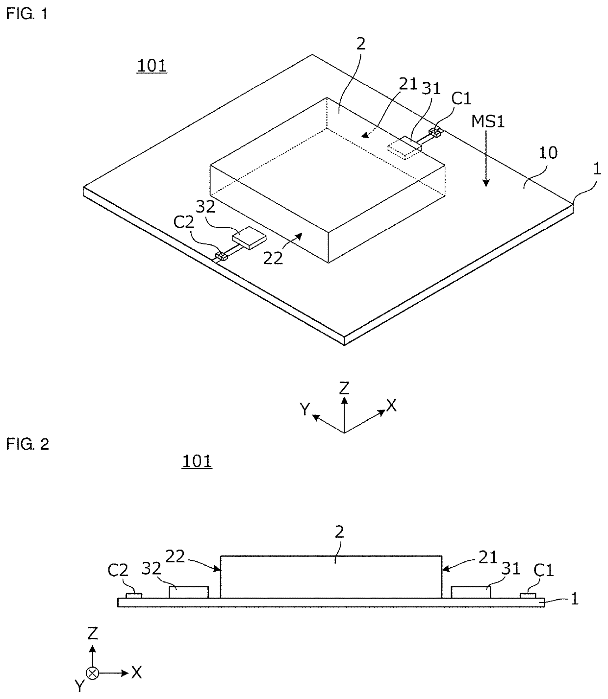
[0034]FIG. 1 is a perspective view of an antenna unit 101 according to a first preferred embodiment of the present invention. The antenna unit 101 is provided in an electronic device. The electronic device may be various electronic devices including, for example, a mobile phone terminal, such as a smart phone or a feature phone, a wearable terminal, such as a smart watch or a smart glass, a mobile personal computer (PC), such as a notebook PC or a tablet PC, an information device, such as a camera, a game machine, or a toy, and an information medium, such as an integrated circuit (IC) tag, a secure digital (SD) card, a subscriber identity module (SIM) card, or an IC card.

[0035]FIG. 2 is a front view of the antenna unit 101. The antenna unit 101 includes a substrate 1, a body 2 that is provided on the substrate 1 and may preferably be a metal body, a first coil antenna 31, a second coil antenna 32, and capacitors C1 and C2. In addition, in the present preferred embodiment, the body 2...

second preferred embodiment

[0064]FIG. 10 is a plan view of an antenna unit according to a second preferred embodiment of the present invention. The second preferred embodiment differs from the first preferred embodiment illustrated in FIG. 3B in the positions of the first coil antenna 31 and the second coil antenna 32.

[0065]Although the first coil antenna 31 is preferably provided at the center or approximate center in the width direction of the first conductive portion 21 and the second coil antenna 32 is preferably provided at the center or approximate center in the width direction of the second conductive portion 22, as described in the first preferred embodiment, a certain degree of freedom is provided to the relative positions between the coil antennas 31 and 32 and the conductive portions 21 and 22.

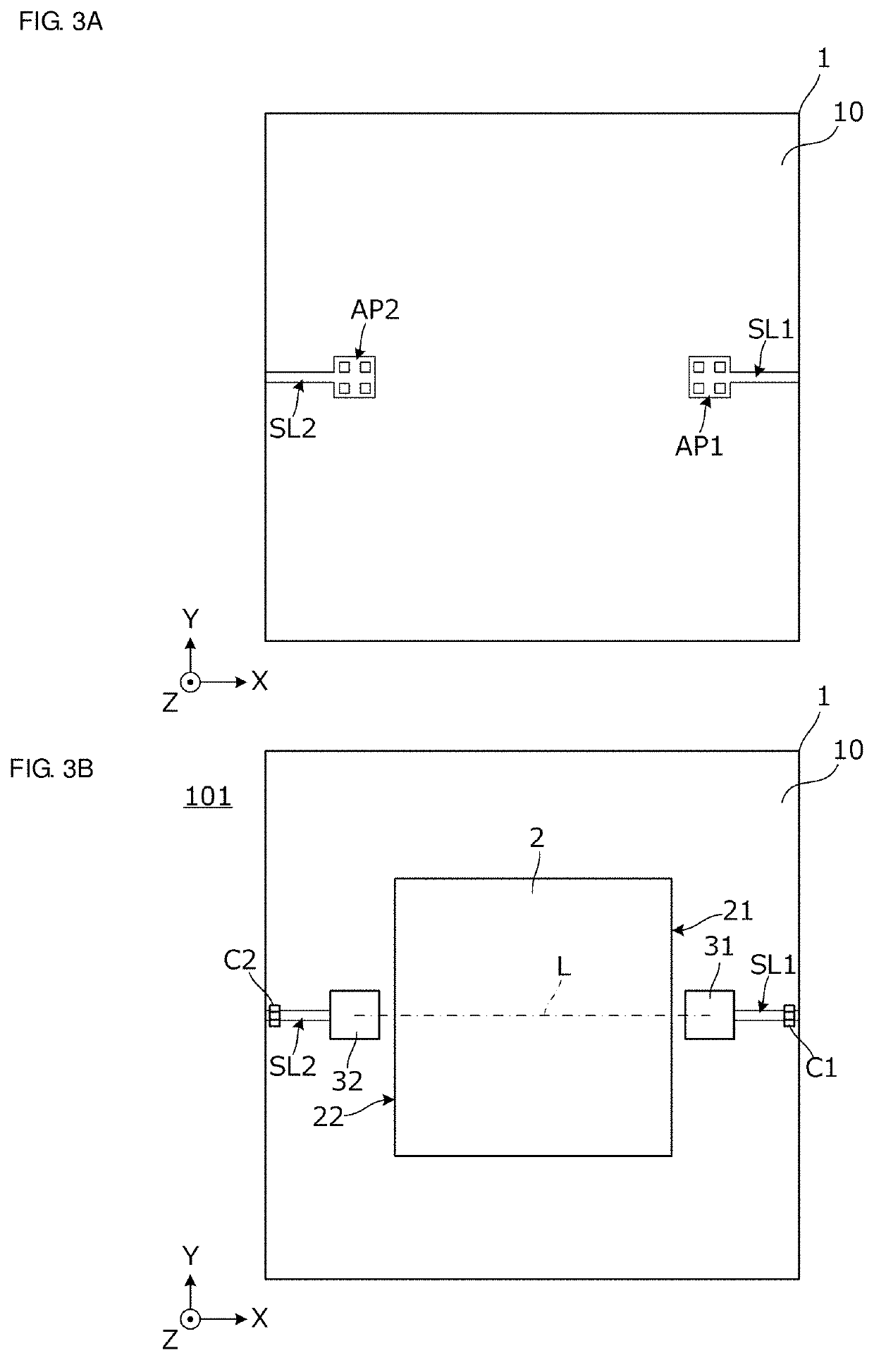
[0066]Referring to FIG. 10, a straight line L-L is a line passing through the winding center of the coil of the first coil antenna 31 and the winding center of the coil of the second coil antenna 32 and the f...

third preferred embodiment

[0068]FIG. 11 is a plan view of an antenna unit according to a third preferred embodiment of the present invention. The third preferred embodiment differs from the second preferred embodiment illustrated in FIG. 10 in the position of the first slit SL1 provided in the planar conductor 10.

[0069]As described in the second preferred embodiment, a certain degree of freedom is provided to the relative position between the coil antennas 31 and 32 and the conductive portions 21 and 22. In addition, a certain degree of freedom is provided to the slits that extend from the positions where the coil antennas 31 and 32 are mounted to the outer edge of the planar conductor 10. As illustrated in FIG. 11, both of the first slit SL1 and the second slit SL2 may be linked to the same side (the left side in the orientation illustrated in FIG. 11) of the planar conductor 10.

[0070]Finally, the description of the above preferred embodiments is for illustrative purposes only in all points and is not inten...


PUM


Abstract

An antenna unit includes a substrate, a body that includes a first conductive portion and a second conductive portion opposed to each other on side surfaces orthogonal or substantially orthogonal to a first main surface of the substrate, and first and second coil antennas the winding axes of which are orthogonal or substantially orthogonal to the first main surface. In a plan view of the first main surface, the first coil antenna is positioned in proximity to the first conductive portion, compared with the second coil antenna, and the second coil antenna is positioned in proximity to the second conductive portion, compared with the first coil antenna. In a plan view of the first main surface, a straight line passing through the first coil antenna and the second coil antenna intersects with the first conductive portion and the second conductive portion.

Description

CROSS REFERENCE TO RELATED APPLICATIONS[0001]This application claims the benefit of priority to Japanese Patent Application No. 2018-025581 filed on Feb. 16, 2018 and is a Continuation Application of PCT Application No. PCT / JP2019 / 003934 filed on Feb. 5, 2019. The entire contents of each application are hereby incorporated herein by reference.BACKGROUND OF THE INVENTION1. Field of the Invention[0002]The present invention relates to an antenna unit used in, for example, a radio-frequency identification (RFID) system or a near field wireless communication system, and an electronic device including the antenna unit.2. Description of the Related Art[0003]International Publication No. 2017 / 057421 discloses an antenna unit that suppresses an occurrence of many magnetic fluxes that do not have interlinkage to a coil antenna of a communication partner side, that is, many magnetic fluxes that do not contribute to communication, among magnetic fluxes passing through the coil opening of the co...

Claims


Application Information

Patent Timeline
IPC IPC(8): H01Q7/00H01Q1/22H05K1/18H01Q1/48G06K19/077
CPCH05K2201/10098H01Q1/48H05K1/181G06K19/07775H01Q1/2208H01Q7/00H05K1/165H05K2201/0715H05K2201/10015H05K2201/10371H05K2201/10037G06K19/07779H04B5/48
Inventor TENNO, NOBUYUKI
Owner MURATA MFG CO LTD
Why Eureka
Try Eureka