

Integrated LTCC mm-wave planar array antenna with low loss feeding network
- Summary
- Abstract
- Description
- Claims
- Application Information
AI Technical Summary
Benefits of technology
Problems solved by technology
Method used
Image

Examples
Embodiment Construction
[0022] The present invention and various advantages thereof will be described with reference to exemplary embodiments in conjunction with the drawings.
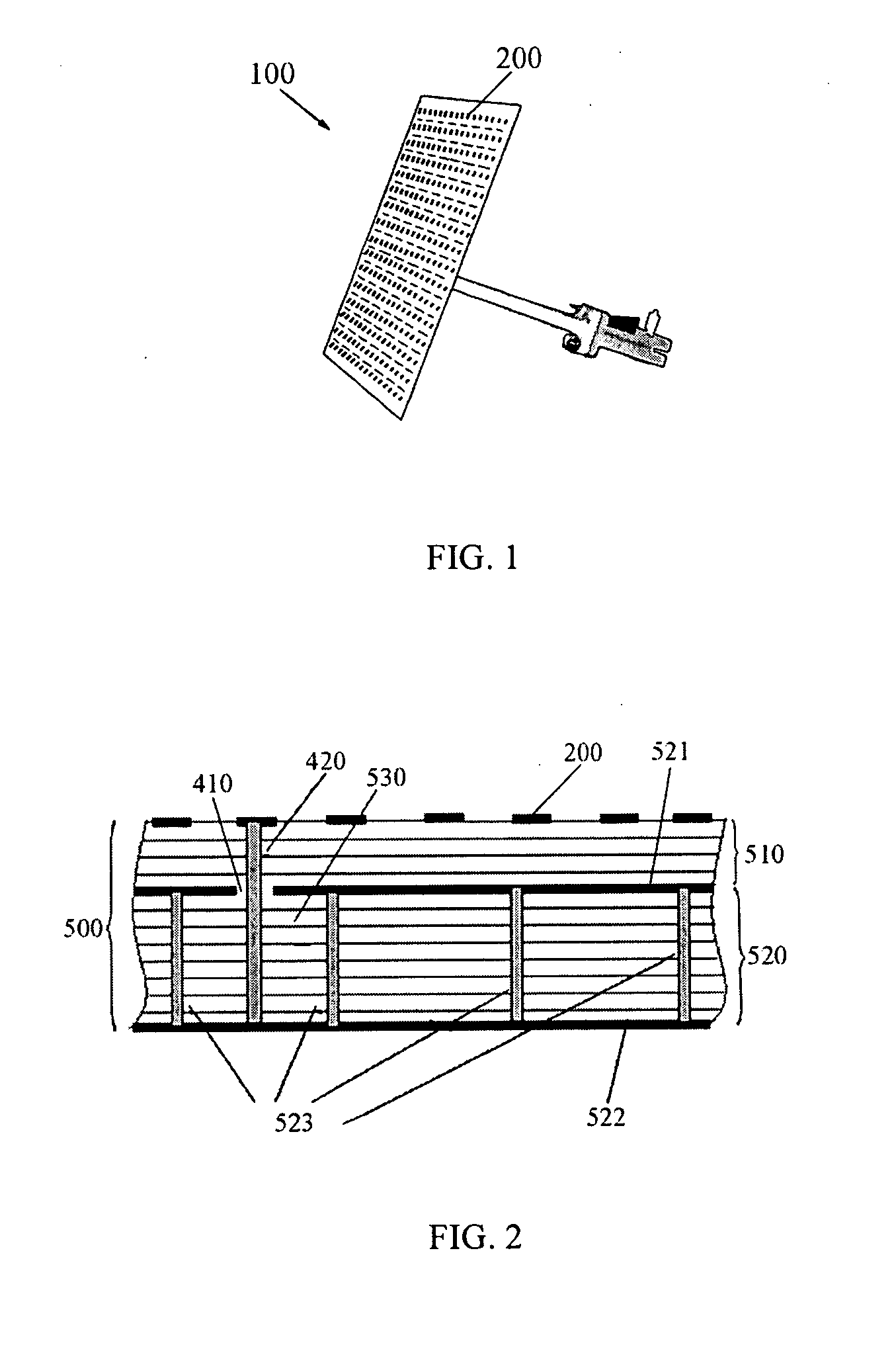
[0023]FIG. 1 shows an array antenna 100 of the present invention. According to the present embodiment, the array antenna 100 comprises 256 quasi-cavity-backed patch (QCBP) antennas 200 including 16 columns and 16 rows, and a multi-layered Low Temperature Co-fired Ceramic (LTCC) substrate 500.
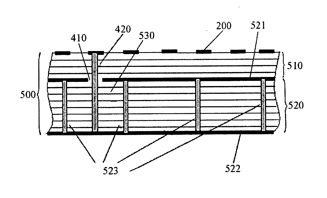
[0024] As shown in FIG. 2, the LTCC substrate 500 of the array antenna 100 comprises a first substrate 510 which further comprises four low temperature co-fired ceramic layers, and a second substrate 520 which further comprises eight low temperature co-fired ceramic layers. The 256 patch antennas 200 are provided on a top surface 511 of the first substrate 510. A bottom ground plane 522 is stacked on the bottom of the second ceramic substrate 520.
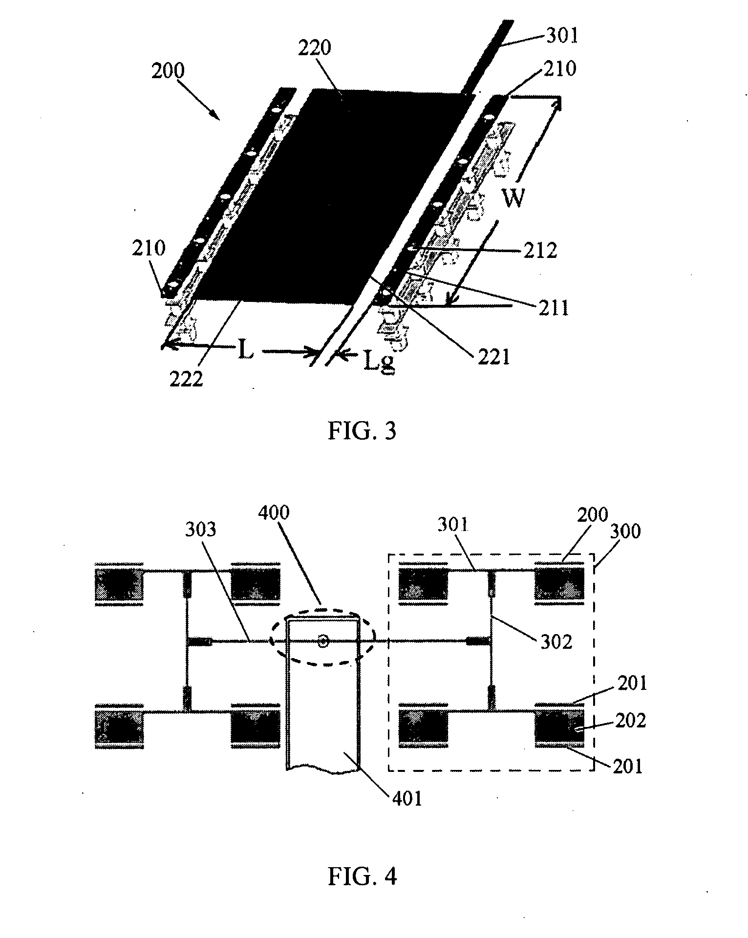
[0025] Referring to FIG. 3, each patch antenna 200 of the array antenna 100 comprises a radiating e...
PUM
 Abstract
Description
Claims
Application Information