Hydraulic Signature Tester

a technology of hydrostatic signature and tester, which is applied in the field of subsea equipment, can solve the problems of adding unnecessary costs and opening the system up to infant mortality of critical equipmen

Active Publication Date: 2011-10-27
THE SUBSEA
View PDF10 Cites 1 Cited by
  • Summary
  • Abstract
  • Description
  • Claims
  • Application Information

AI Technical Summary

Problems solved by technology

This not only adds needless costs, it also opens the system up for infant mortality of critical equipment due to needless repairs.

Method used


Image

  • Hydraulic Signature Tester
  • Hydraulic Signature Tester

Examples


Embodiment Construction

[0008]While the making and using of various embodiments of the present invention are discussed in detail below, it should be appreciated that the present invention provides many applicable inventive concepts that can be embodied in a wide variety of specific contexts. The specific embodiments discussed herein are merely illustrative of specific ways to make and use the invention and do not delimit the scope of the invention.

[0009]To facilitate the understanding of this invention, a number of terms are defined below. Terms defined herein have meanings as commonly understood by a person of ordinary skill in the areas relevant to the present invention. Terms such as “a”, “an” and “the” are not intended to refer to only a singular entity, but include the general class of which a specific example may be used for illustration. The terminology herein is used to describe specific embodiments of the invention, but their usage does not delimit the invention, except as outlined in the claims.

[...


PUM


Abstract

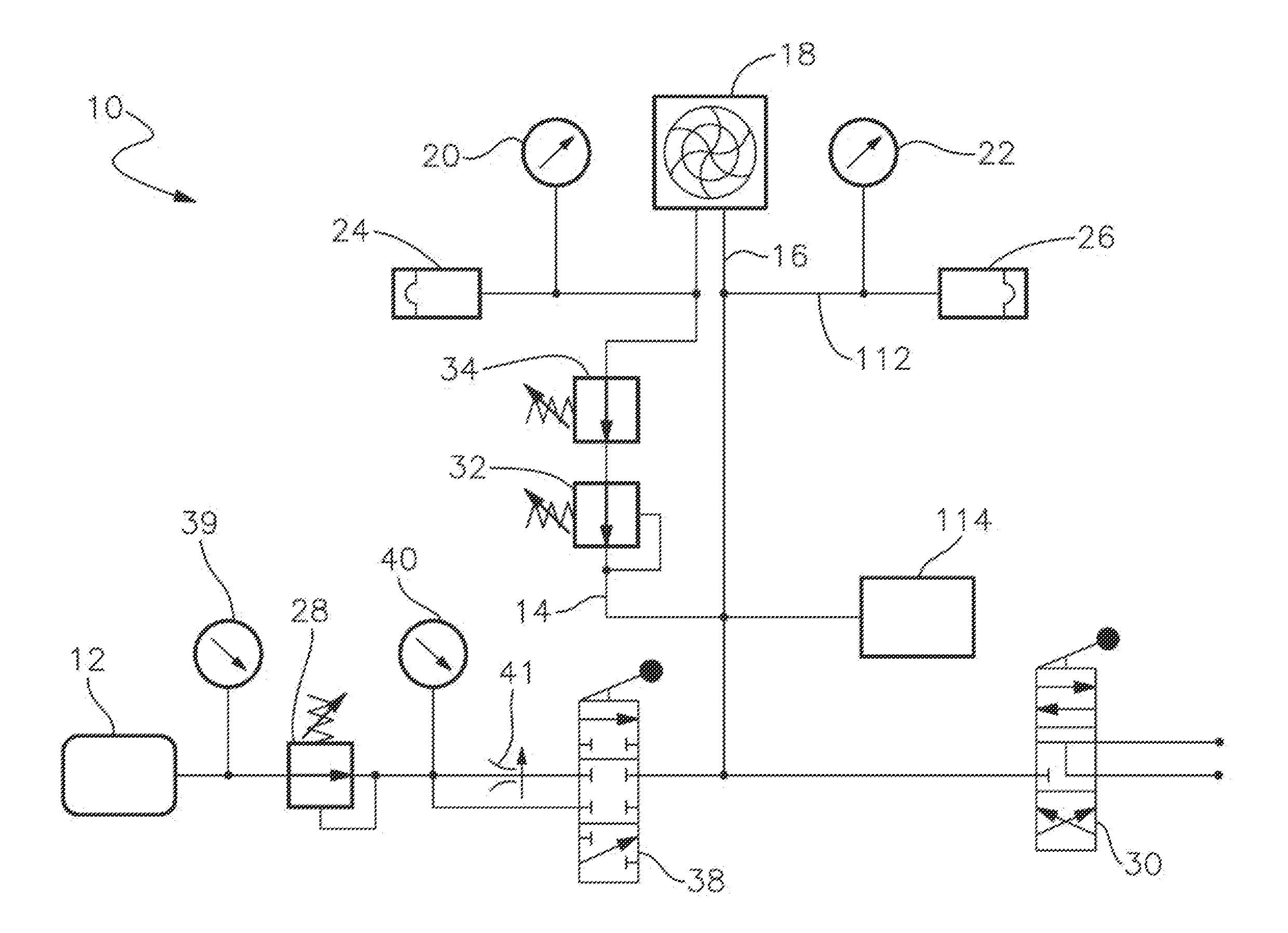
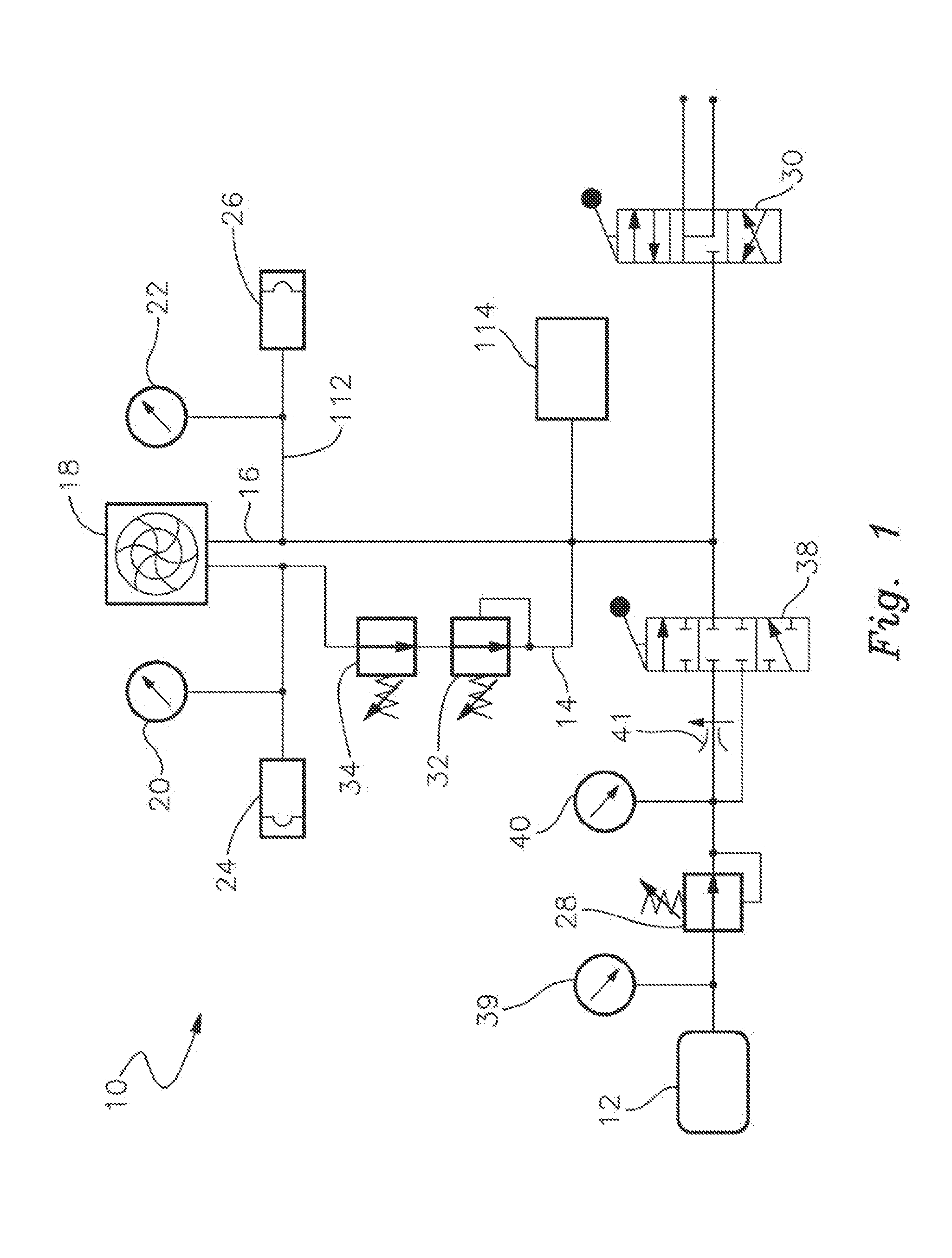
The present invention provides a subsea apparatus for testing a hydraulic signature which has a fluid supply, a first pressure line coupled to the fluid supply, a second pressure line coupled to the fluid supply; and a pressure recording device operatively coupled to both the first pressure line and the second pressure line. A pressure recording device is capable of storing pre-determined pressure data representative of said pressure lines. The first pressure line functions at a lower pressure than the second pressure line while a pressure recording device records data to allow comparison of actual pressure data on the first and second pressure lines with said stored data.

Description

FIELD OF INVENTION[0001]The present invention relates in general to the field of subsea equipment.BACKGROUND ART[0002]The present invention relates to methods and systems for subsea energy extraction. In particular, the present invention relates to a hydraulic signature tester for assessment and monitoring of pressure systems.[0003]Various mechanisms have been employed to prevent failure of subsea components due in part to maintenance being performed normally on a time related basis rather than a condition based scenario. This not only adds needless costs, it also opens the system up for infant mortality of critical equipment due to needless repairs.[0004]Thus there exists a need for an apparatus that is capable of dynamically measuring fluid flow anomalies via pressure and time constraints during normal maintenance checks to fully analyze the condition of the equipment to determine if a repair is required. After repairs, the system of a preferred embodiment of the invention is used...

Claims


Application Information

Patent Timeline
Patent Type & Authority Applications(United States)
IPC IPC(8): E21B47/06E21B47/10
CPCF15B20/00E21B47/10E21B47/001
Inventor MCMILES, BARRY J.
Owner THE SUBSEA
Why Eureka
Try Eureka