
Image processing apparatus, image processing method, and storage medium

a technology of image processing and image processing method, which is applied in the field of image processing apparatus, image processing method and storage medium for processing images, can solve the problems of inability to display images of cross sections corresponding to each other, and the inability to generate an appropriate cross section image in one data set that corresponds to a cross section image designated in the other data s

Inactive Publication Date: 2011-10-27
CANON KK
View PDF5 Cites 45 Cited by
  • Summary
  • Abstract
  • Description
  • Claims
  • Application Information

AI Technical Summary

Benefits of technology

The present invention provides an image processing apparatus and method for processing an image by deforming a first 3D image to a second 3D image and obtaining a relation to perform rigid transformation such that a region of interest in the first 3D image overlaps a region in the second 3D image. This allows for the obtaining of a cross section image of the region of interest in the second 3D image and a cross section image of the region of interest in the first 3D image that corresponds to the orientation of the cross section image in the second 3D image. The technical effect of this invention is improved image processing for better visualization and analysis of 3D images.

Problems solved by technology

However, in the technique disclosed in Japanese Patent Laid-Open No. 2008-073305, common cross sections are respectively extracted after deforming a current 3D image and a past 3D image thereof into the same shape, and therefore there is an issue that the images of the cross sections corresponding to each other cannot be displayed while maintaining their mutually different shapes.
In addition, in the technique of Japanese Patent Laid-Open No. 2009-090120, image slices are simply selected from among image data sets, and thus except for special cases, there is an issue that with respect to a cross section image designated in one of data set, it is impossible to generate an appropriate cross section image in the one data set that corresponds to a cross section image designated in the other data set.

Method used


Image

  • Image processing apparatus, image processing method, and storage medium
  • Image processing apparatus, image processing method, and storage medium
  • Image processing apparatus, image processing method, and storage medium

Examples


first embodiment

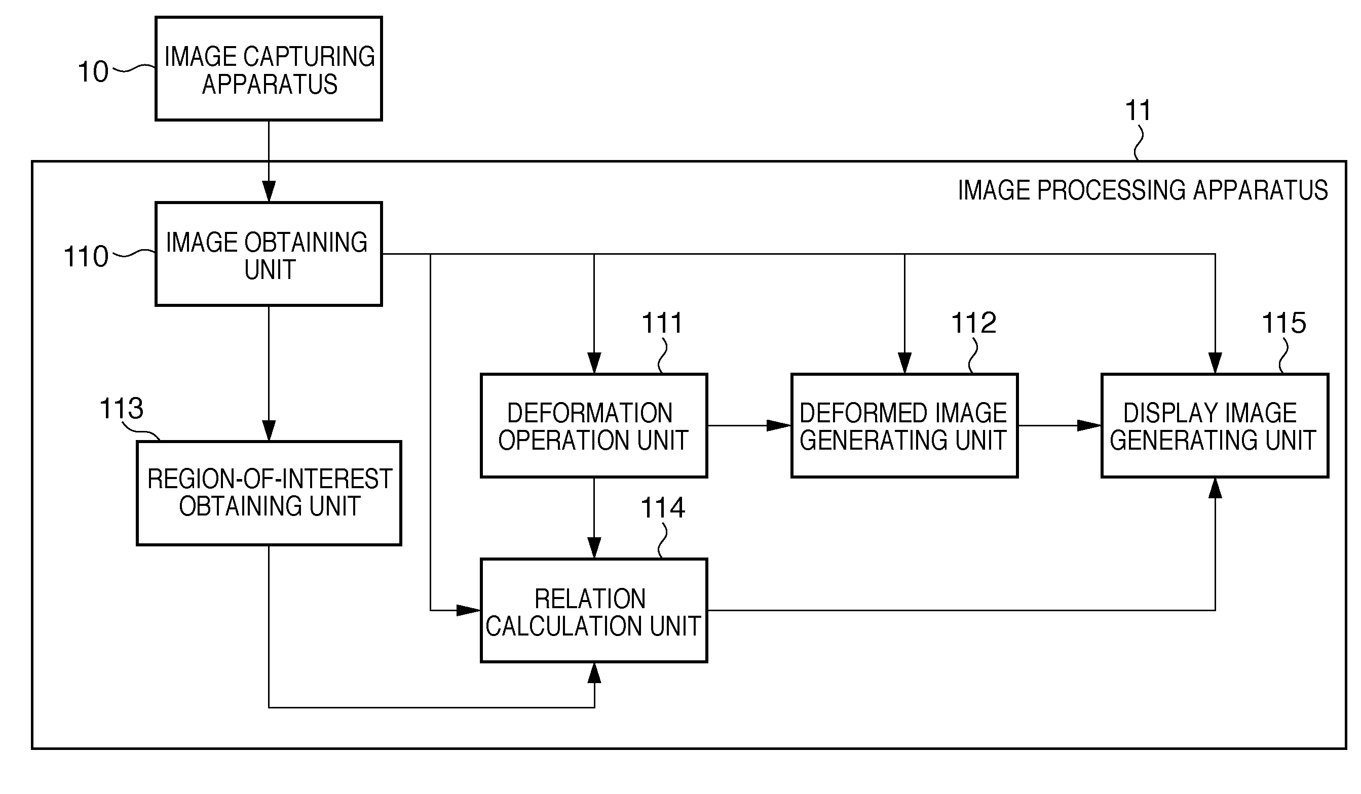
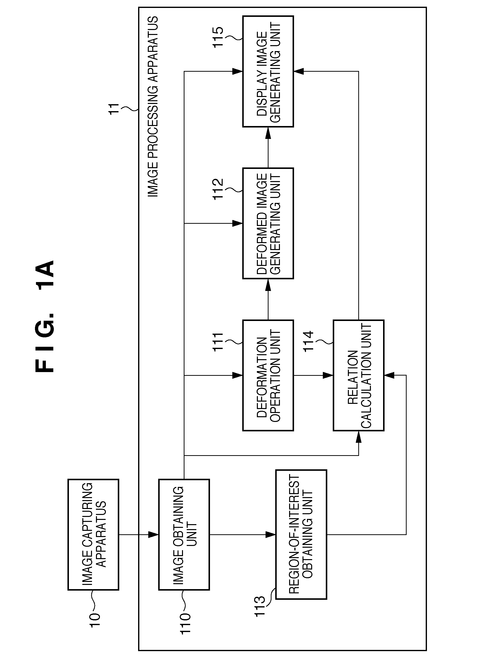
[0026]An image processing apparatus according to the present embodiment virtually generates a 3D image in a second deformation state by performing deformation on a 3D image captured in a first deformation state. Then, cross section images containing a region of interest are generated from the respective 3D images, and the generated images are displayed side by side. Note that in the present embodiment, a human breast is the main target object. The case in which an MRI image of a breast is obtained and a lesion portion in the breast serves as a region of interest will be described as an example. Also in the present embodiment, for example, the first deformation state is a state in which a subject is in a face-down state (prone position) with respect to the direction of gravitational force, and the second deformation state is a state in which a subject is in a face-up state (supine position) with respect to the direction of gravitational force. The first deformation state is a state i...

second embodiment

[0059]Transformation calculation processing performed in the transformation calculation unit 1143 may be processing other than the processing described above. For example, the corresponding point of the center position 401 of the region of interest may be calculated using a method similar to that in step S3002, and a parallel translation component of the rigid transformation may be determined such that these two points match. Specifically, the displacement field T(xsc, ysc, zsc) at the center position 401 (coordinate Xsc) of the region of interest may be used as the parallel translation component of the rigid transformation. In this case, when calculating the matrix Trigid shown in Equation 1 that minimizes the sum e of errors, a configuration is possible in which the parallel translation component of Trigid is fixed to the above value, and only the rotation component is obtained as an unknown parameter. In this manner, the center positions of the region of interest of the third 3D ...

third embodiment

[0062]With the first and second embodiments, the case is described in which a rigid transformation that approximates a change in the position and orientation of the region of interest in the 3D images before and after transformation is calculated in advance. However, the present invention is not limited to this. An image processing apparatus of the present embodiment dynamically changes the method for calculating a rigid transformation depending on the position and orientation of the designated cross section. Only portions of the image processing apparatus of the present embodiment that are different from the first and second embodiments are described below.

[0063]A configuration of the image processing apparatus of the present embodiment is described below with reference to FIG. 5. Note that the same elements as those in FIG. 1A are assigned the same reference numerals, and are not described here. As shown in FIG. 5, an image processing apparatus 11 of the present embodiment is conn...


PUM


Abstract

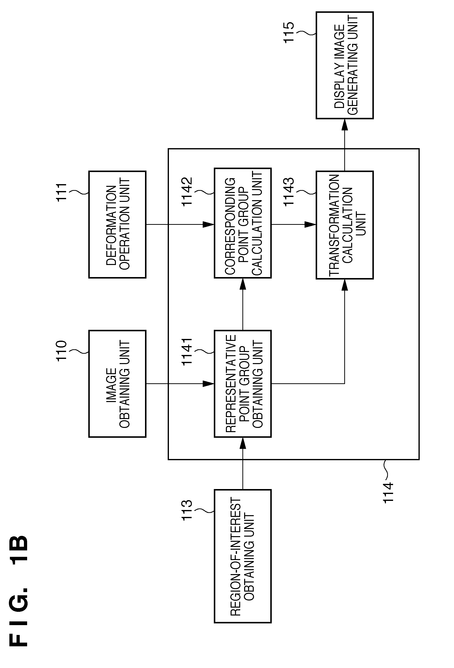
An image processing apparatus comprises: a deformation unit adapted to deform a first 3D image to a second 3D image; a calculation unit adapted to obtain a relation according to which rigid transformation is performed such that a region of interest in the first 3D image overlaps a region in the second 3D image that corresponds to the region of interest in the first 3D image; and an obtaining unit adapted to obtain, based on the relation, a cross section image of the region of interest in the second 3D image and a cross section image of the region of interest in the first 3D image that corresponds to the orientation of the cross section image in the second 3D image.

Description

BACKGROUND OF THE INVENTION[0001]1. Field of the Invention[0002]The present invention relates to an image processing apparatus, an image processing method and a storage medium for processing images captured by a medical image acquisition apparatus. Particularly, the present invention relates to an image processing apparatus, an image processing method and a storage medium for performing processing for associating a plurality of cross section images with each other.[0003]2. Description of the Related Art[0004]In the mammary gland medical field, there are cases where image diagnosis is performed in a procedure after the position of a lesion site in a breast is identified in an image captured by a magnetic resonance imaging apparatus (MRI apparatus), the state of the lesion site is observed by an ultrasound image diagnosis apparatus (ultrasound device). Here, according to a general capturing protocol employed in the mammary gland medical field, capturing by an MRI apparatus is often pe...

Claims


Application Information

Patent Timeline
Patent Type & Authority Applications(United States)
IPC IPC(8): G06K9/00
CPCG06K9/6206G06T2207/30068G06T2207/10088G06T7/0028G06T7/33G06V10/754
Inventor ISHIKAWA, RYOSATOH, KIYOHIDEENDO, TAKAAKI
Owner CANON KK
Learn More