Inkjet printing apparatus
a printing apparatus and inkjet technology, applied in printing, typewriters, other printing apparatus, etc., can solve the problems of reducing throughput, limiting the temperature and airflow of the fixing apparatus, and wasting time, so as to shorten the wait time, shorten the time required for fixing ink, and increase throughput
- Summary
- Abstract
- Description
- Claims
- Application Information
AI Technical Summary
Benefits of technology
Problems solved by technology
Method used
Image

Examples
first embodiment
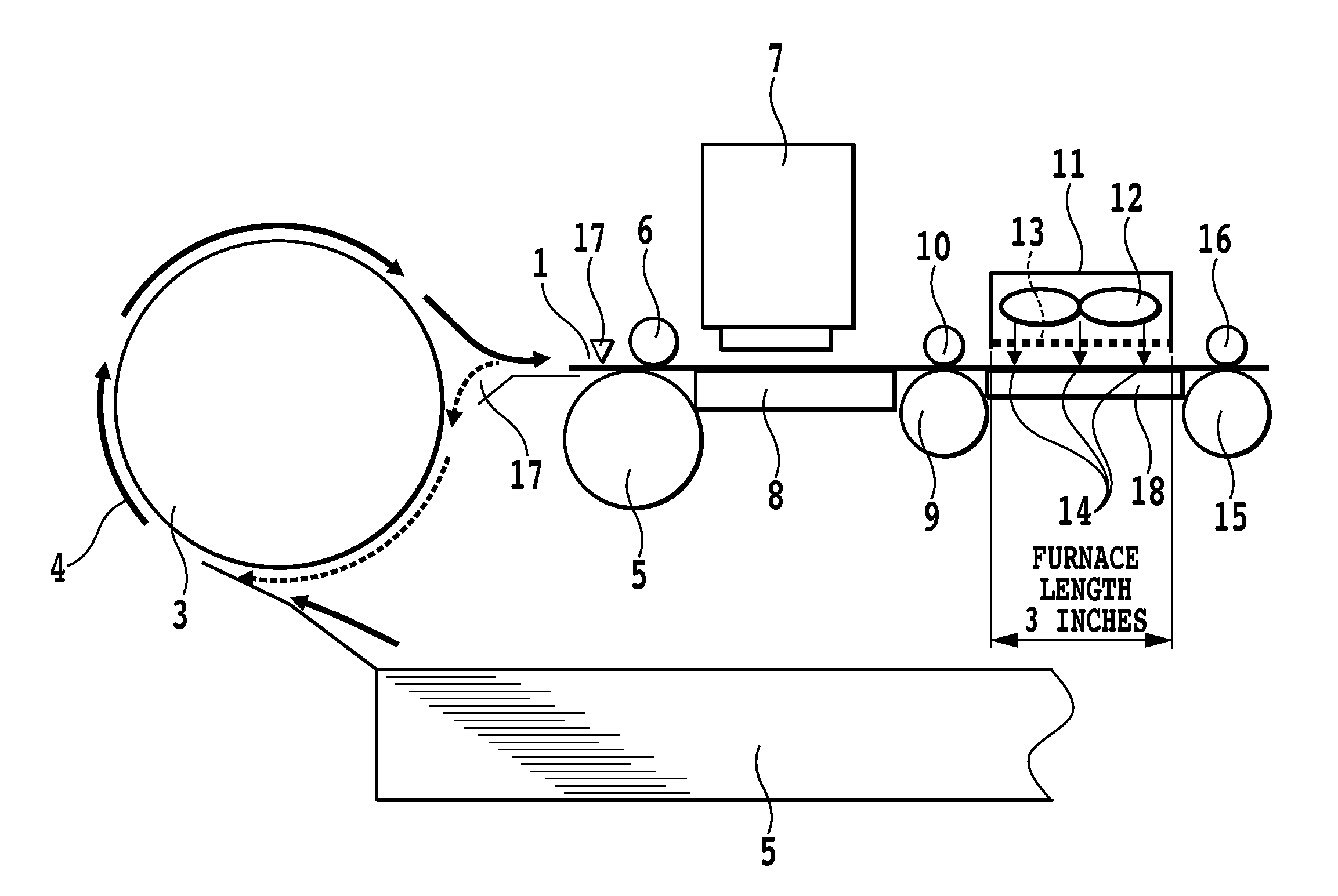
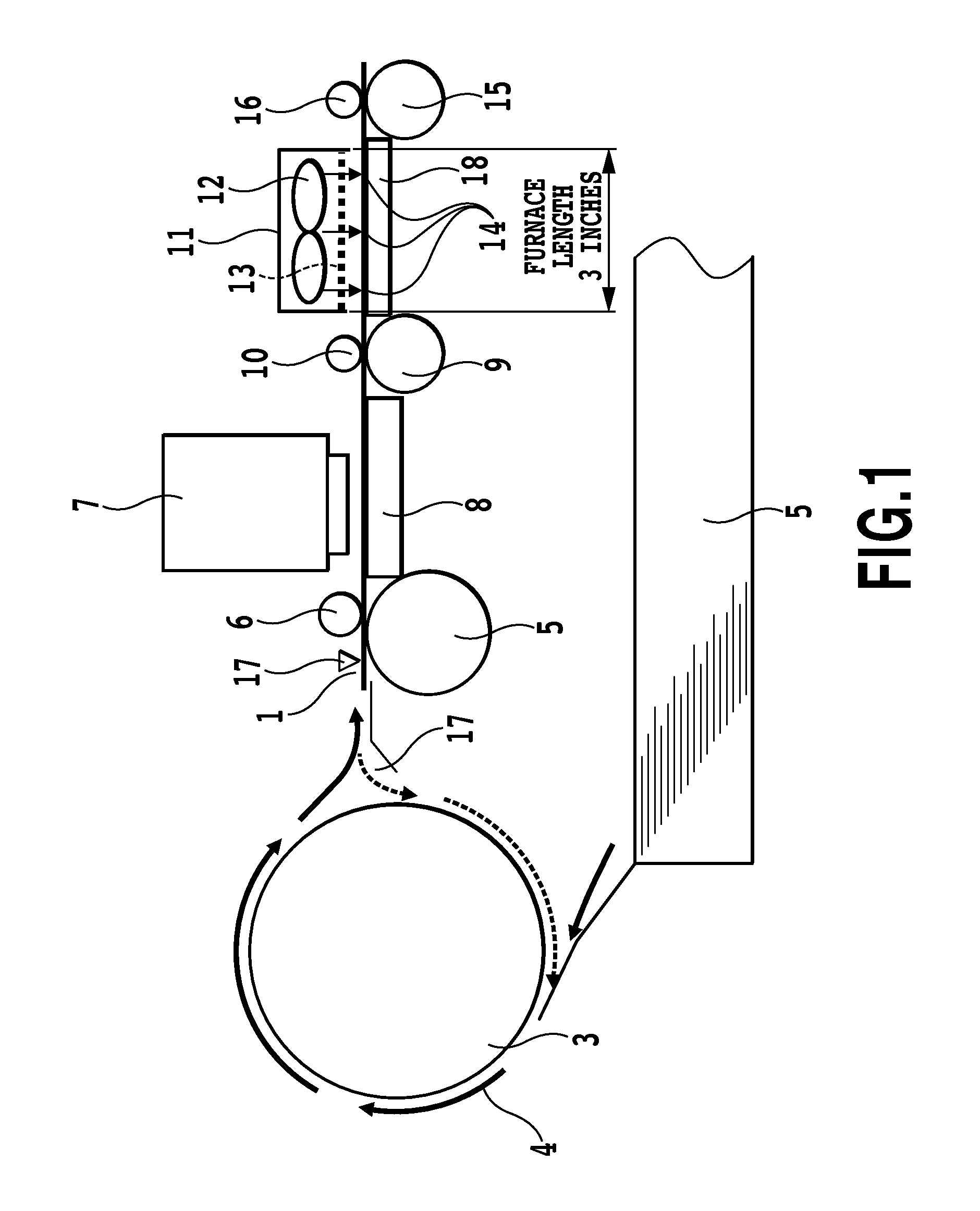
[0032]FIG. 1 is a configuration diagram of an inkjet printing apparatus (printer) of the present embodiment. This printer is able to print an image onto the front side of a sheet (first side), and then reverse the sheet and print an image onto the back side (second side).
[0033]A maximum of 250 sheets 1 can be set in a feed cassette 2. One sheet at a time is picked up by a feed roller and separating means not illustrated. A U-turn conveyance unit 3, together with a passive conveyance roller not illustrated, conveys a sheet in the direction of the solid arrows 4. This U-turn conveyance unit 3 also doubles as a duplex reversal unit. An inkjet print head 7 constitutes a printing unit. Any of a technique using a heating element, a technique using a piezoelectric element, a technique using a MEMS element, a technique using an electrostatic element, etc. is applicable as the inkjet technique.
[0034]A sheet 1 fed along the solid arrows 4 is held between an LE roller 5 and a pinch roller 6, a...
second embodiment
[0058]FIG. 6 is a schematic diagram of a fixing furnace and the vicinity of a duplex reversal unit in an inkjet printer of the second embodiment as viewed from the side. In FIG. 6, 200 is a sheet. A maximum of 250 sheets can be set in a feed cassette 201. One sheet at a time is picked up by a feed roller and separating means not illustrated. 202 is a U-turn conveyance unit which, together with a passive conveyance roller not illustrated, conveys a sheet in the direction of the solid arrows 203. This U-turn conveyance unit 202 also doubles as a duplex reversal unit. A sheet 200 fed along the solid arrows 203 is held between an LF roller 204 and a pinch roller 205, and conveyed directly underneath a print head 206. An LF encoder not illustrated is coaxially coupled to the LF roller 209, and is able to detect at a resolution of 1 / 2400 inch by converting rotation of the LF roller 204 into sheet feed distance. 228 is a sheet passage sensor (hereinafter, sheet sensor) disposed immediately...
third embodiment
[0062]The third embodiment is a configuration that adds to the first embodiment a function enabling the operator to specify a drying fixing level that prescribes the degree of drying of a sheet onto which ink has been ejected.
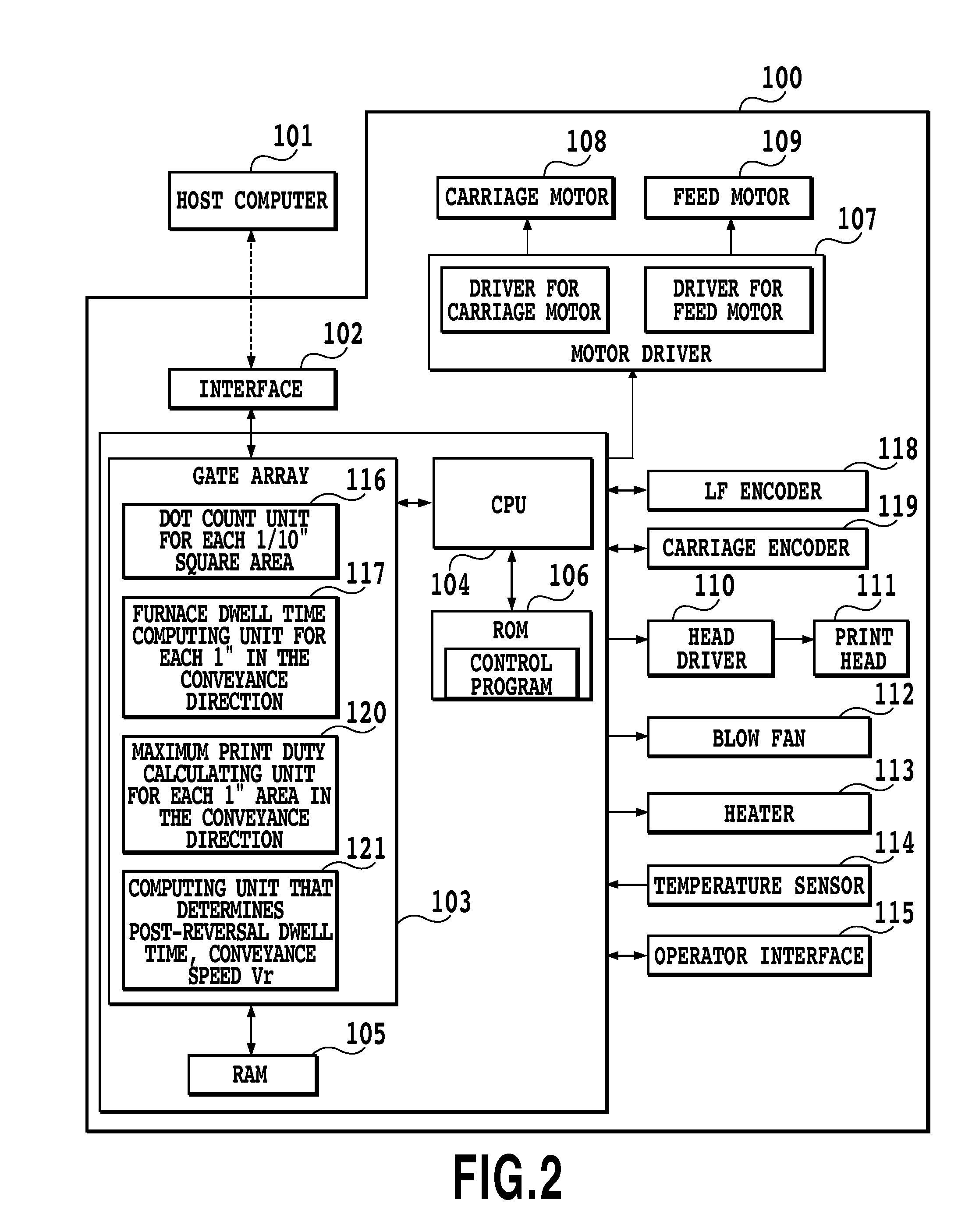
[0063]FIG. 7 illustrates an exemplary screen for when the operator specifies a drying fixing level on a printer driver screen on a host computer. FIG. 8 is a block diagram illustrating a control configuration in the present embodiment. Regarding FIG. 8, only the portions that have been added to the block diagram in FIG. 2 described in the first embodiment are described, while the same reference numbers are used for the same function units as FIG. 2.
[0064]In FIG. 7, 300 is a settings diagram for when a drying level settings screen is opened from a printer settings screen on a host computer. Using a mouse or other device, a pointer 301 can be aligned with the three stages “Standard”, “Dry 1”, and “Dry 2” in the direction of the arrow 303 along a drying level bar ...
PUM
 Abstract
Description
Claims
Application Information
 - R&D
- Intellectual Property
- Life Sciences
- Materials
- Tech Scout
- Unparalleled Data Quality
- Higher Quality Content
- 60% Fewer Hallucinations
Browse by: Latest US Patents, China's latest patents, Technical Efficacy Thesaurus, Application Domain, Technology Topic, Popular Technical Reports.
© 2025 PatSnap. All rights reserved.Legal|Privacy policy|Modern Slavery Act Transparency Statement|Sitemap|About US| Contact US: help@patsnap.com