
Lock cylinder assembly

a technology of lock cylinder and lock body, which is applied in the direction of cylinder locks, building locks, construction, etc., can solve the problems of known lock cylinder lacking burglarproof and security seriously in a locked condition, and achieve the effects of strengthening the lock cylinder structure, enhancing burglarproof and security of the lock cylinder assembly, and increasing the difficulty of unlocking

Inactive Publication Date: 2011-11-10
TAIWAN FU HSING INDAL
View PDF6 Cites 12 Cited by
  • Summary
  • Abstract
  • Description
  • Claims
  • Application Information

AI Technical Summary

Benefits of technology

[0004]The primary object of the present invention is to provide a lock cylinder assembly comprising at least a cylinder body, a plug, a plurality of pin sets and a position block, wherein the plug comprising a keyhole is rotatable within the cylinder body between a locked position and an unlocked position, the pin sets enable the plug disposed relative to the cylinder body to change state between a non-interference state and an interference state, the position block enables the plug disposed relative to the cylinder body to change state between the non-interference state and the interference state, and at least one of the pin sets and the position block is in the interference state to disable the lock cylinder from the locked position without a matched key in the keyhole. If an unmatched key is inserted into the keyhole of the plug with opportune beat and turn to unlock in a locked condition, the unmatched key beats and moves the position block to make the plug maintained in the locked position and prevent the plug from rotation. Accordingly, because the unmatched key cannot disengage the position block from the plug, a burglary attempting to turn the plug violently for unlocking with an unmatched key may be effectively prevented. In addition, the present invention also utilizes the position block to strengthen lock cylinder structure and increase unlocking difficulty for an unmatched key and thereby widely enhancing burglar-proof and security of the lock cylinder assembly.

Problems solved by technology

Because of the arrangement between the upper pins and the lower pins, the plug is position-limited by the upper pins or the lower pins unable to turn in the cylinder body, which may function as position-limitation and anti-turn.
However, when burglar attempts to illegally unlock lock cylinder of known lock device, he might insert an unmatched key into a keyhole of the plug and provides an opportune beat on the lock, in which the lower pins in the plug are hit by the bitting of the unmatched key to simultaneously hit the upper pins between the cylinder body and the plug, that makes the upper pins move to the cylinder body, and then the plug is opportunely turned by the unmatched key to unlock easily, so that the known lock cylinder lacks in burglar-proof and security seriously in a locked condition.

Method used


Image

  • Lock cylinder assembly
  • Lock cylinder assembly
  • Lock cylinder assembly

Examples


Embodiment Construction

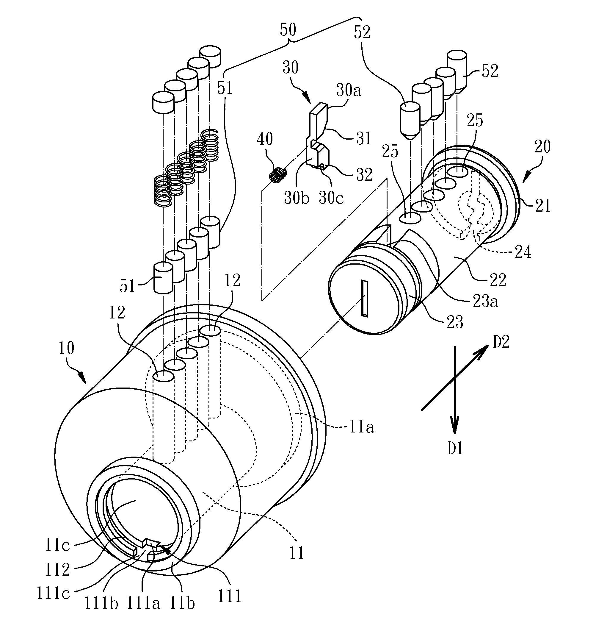
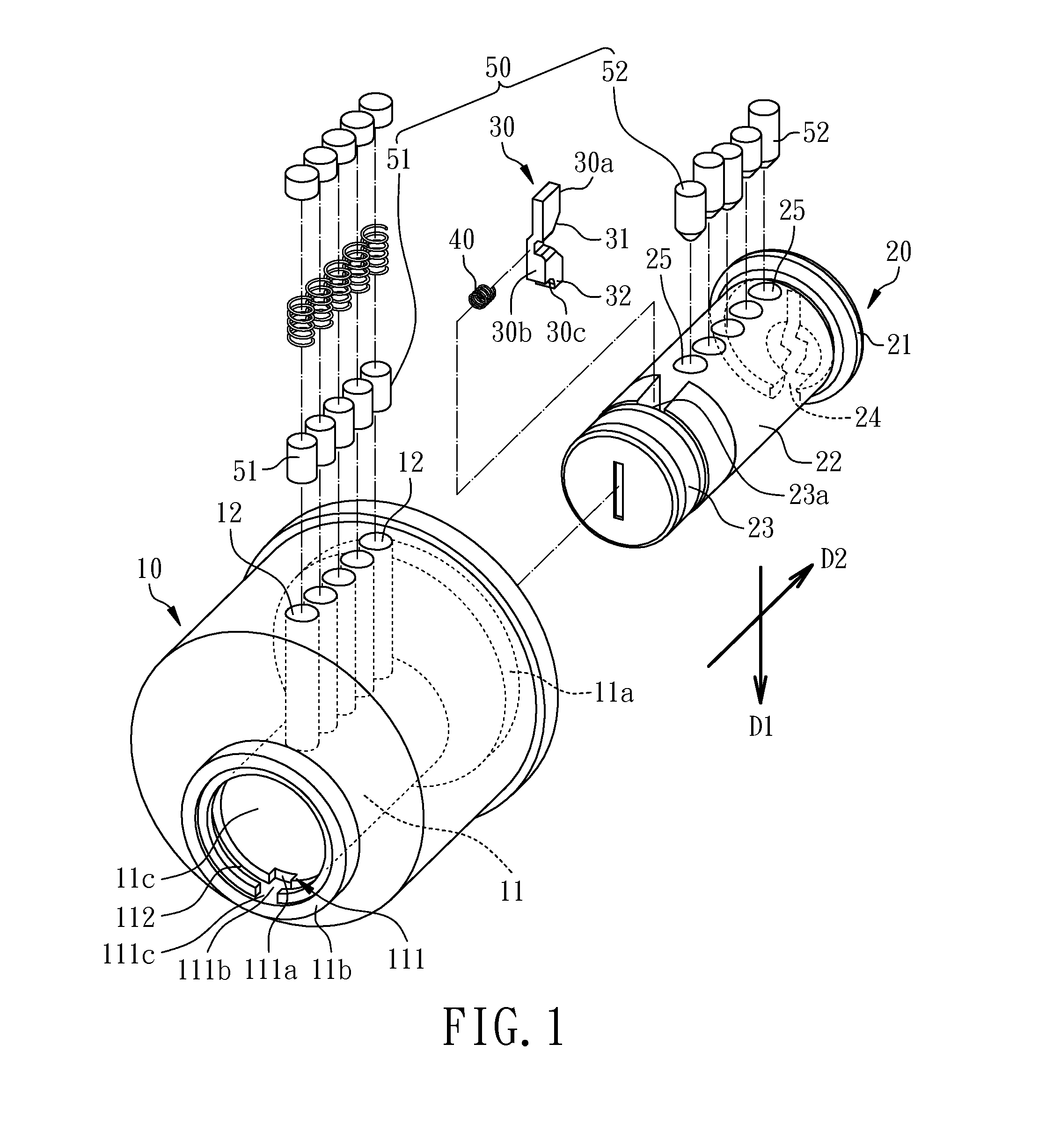
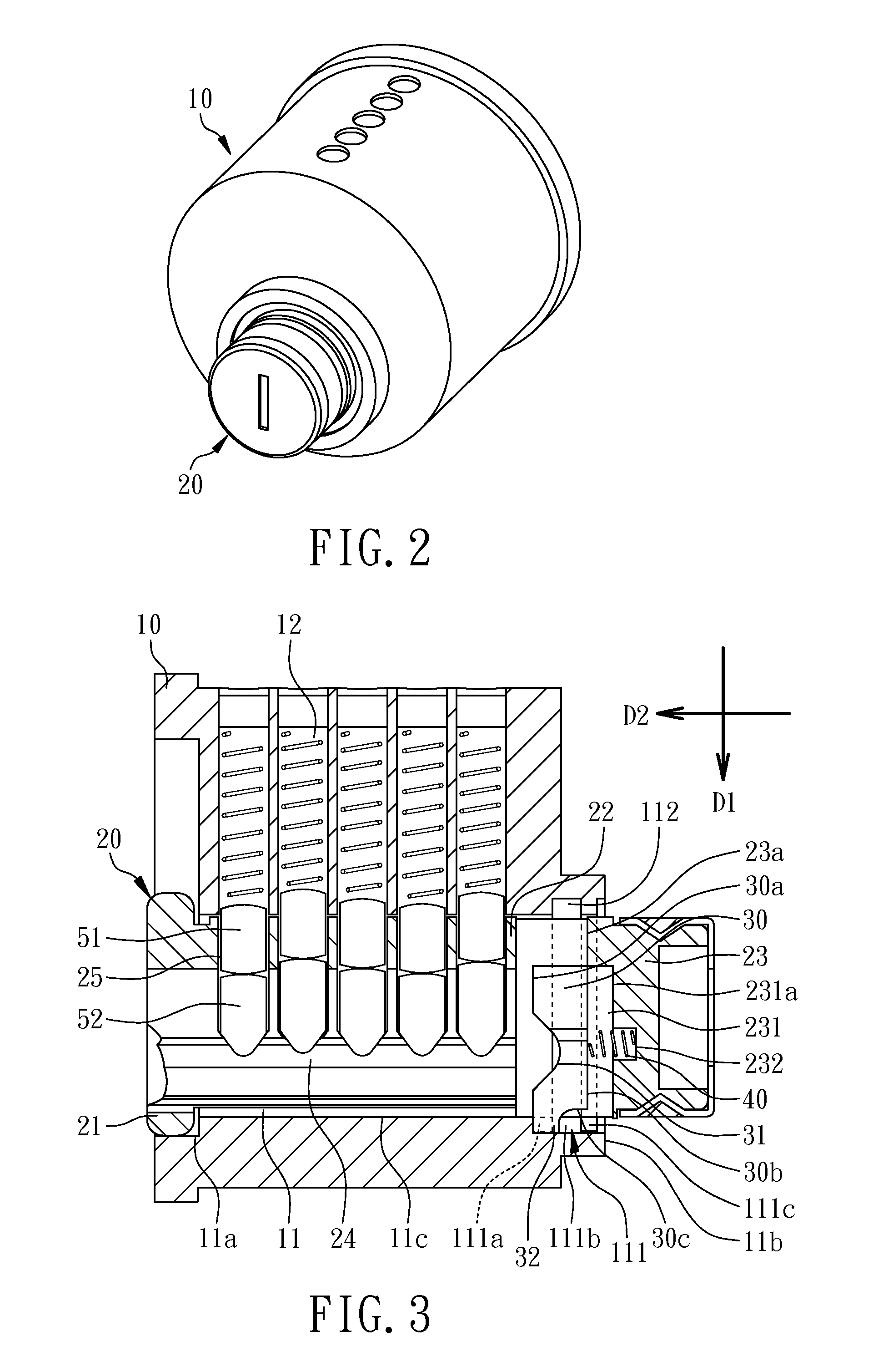
[0015]Referring to FIGS. 1, 2 and 3, a lock cylinder assembly in accordance with the first preferred embodiment of the present invention comprises a cylinder body 10, a plug 20, a position block 30, a resilient member 40 and a plurality of pin sets 50. The cylinder body 10 is a hollow cylinder in various appearances having a hollow cylinder portion 11 and a plurality of upper pin holes 12 in communication with the hollow cylinder portion 11. The hollow cylinder portion 11 has a first end 11a, a second end 11b opposite to the first end 11a, an inside wall 11c, an axial groove 111 located at the second end 11b and a radial groove 112 in communication with the axial groove 111, wherein the axial groove 111 and the radial groove 112 recess from the inside wall 11c. In this embodiment, the axial groove 111 comprises a first limiting area 111a, an overlapping area 111b and a second limiting area 111c, wherein the axial groove 111 communicates with and intersects the radial groove 112 at t...


PUM


Abstract

A lock cylinder assembly comprises a cylinder body, a plug, a plurality of pin sets and a position block, wherein the plug comprising a keyhole is rotatable within the cylinder body between a locked position and an unlocked position, the pin sets enable the plug disposed relative to the cylinder body to change state between a non-interference state and an interference state, the position block enables the plug disposed relative to the cylinder body to change state between the non-interference state and the interference state, and at least one of the pin sets and the position block is situated in the interference state to disable the lock cylinder from the locked position without a matched key in the keyhole.

Description

CROSS REFERENCE TO RELATED APPLICATIONS[0001]This application is a continuation-in-part of U.S. patent application Ser. No. 12 / 149,688, filed on May 6, 2008, and for which priority is claimed under 35 U.S.C. §120, the entire contents of which are hereby incorporated by reference.FIELD OF THE INVENTION[0002]The present invention is generally relating to a lock cylinder, more particularly to a lock cylinder assembly that utilizes position block for obtaining anti-prying and anti-hitting efficiency.BACKGROUND OF THE INVENTION[0003]The known lock cylinder mainly comprises a cylinder body, a plug and a pin set, the cylinder body and the plug almost dispose pins, wherein the cylinder body disposes a plurality of upper pins having a same height and the plug disposes a plurality of lower pins having different heights. Because of the arrangement between the upper pins and the lower pins, the plug is position-limited by the upper pins or the lower pins unable to turn in the cylinder body, whi...

Claims


Application Information

Patent Timeline
Patent Type & Authority Applications(United States)
IPC IPC(8): E05B27/02
CPCE05B27/00E05B27/0032E05B27/08E05B27/0057E05B27/0042Y10T70/7605
Inventor HUANG, CHAO-MINGCHEN, CHI-MING
Owner TAIWAN FU HSING INDAL
Learn More