System for reducing head space in a pressure cyclone

a technology of head space and pressure cyclone, which is applied in the direction of reversed direction vortex, vortex flow apparatus, separation process, etc., can solve the problems of significant reduction in separation process efficiency, tendency to fail or crack, and is not unheard of to employ pressure cyclone in low-pressure environments

Active Publication Date: 2011-11-10
KELLOGG BROWN & ROOT LLC
View PDF0 Cites 5 Cited by
  • Summary
  • Abstract
  • Description
  • Claims
  • Application Information

AI Technical Summary

Problems solved by technology

However, it is nonetheless not unheard of to employ pressure cyclones in low-pressure environments.
However, the convex top head design essentially creates a void area between the tangential inlet and the top head where the vortex can be significantly disturbed, thereby resulting in a significant reduction in efficiency of the separation process.
Likewise, the casing surrounding the tangential inlet has often been designed with square or rectangular features that also have a tendency to fail or crack under ex

Method used


Image

  • System for reducing head space in a pressure cyclone
  • System for reducing head space in a pressure cyclone
  • System for reducing head space in a pressure cyclone

Examples


Embodiment Construction

[0019]A detailed description will now be provided. Each of the appended claims defines a separate invention, which for infringement purposes is recognized as including equivalents to the various elements or limitations specified in the claims. Depending on the context, all references below to the “invention” may in some cases refer to certain specific embodiments only. In other cases it will be recognized that references to the “invention” will refer to subject matter recited in one or more, but not necessarily all, of the claims. Each of the inventions will now be described in greater detail below, including specific embodiments, versions and examples, but the inventions are not limited to these embodiments, versions or examples, which are included to enable a person having ordinary skill in the art to make and use the inventions, when the information in this patent is combined with publicly available information and technology.

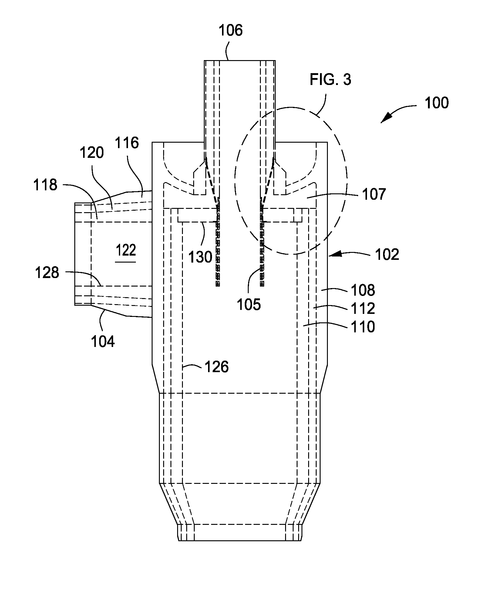
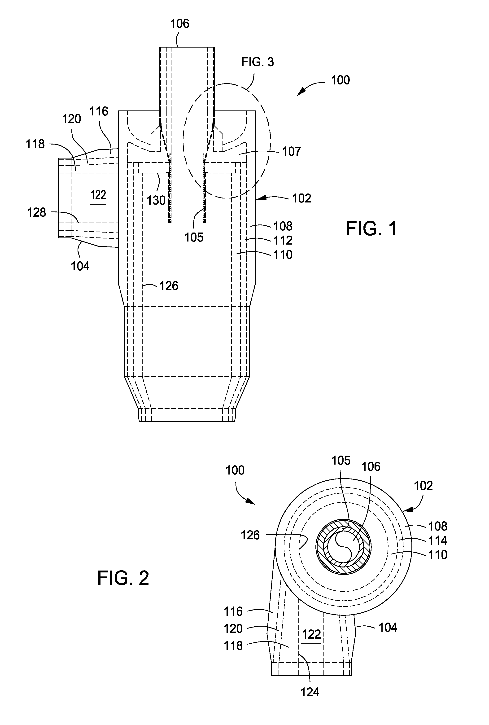
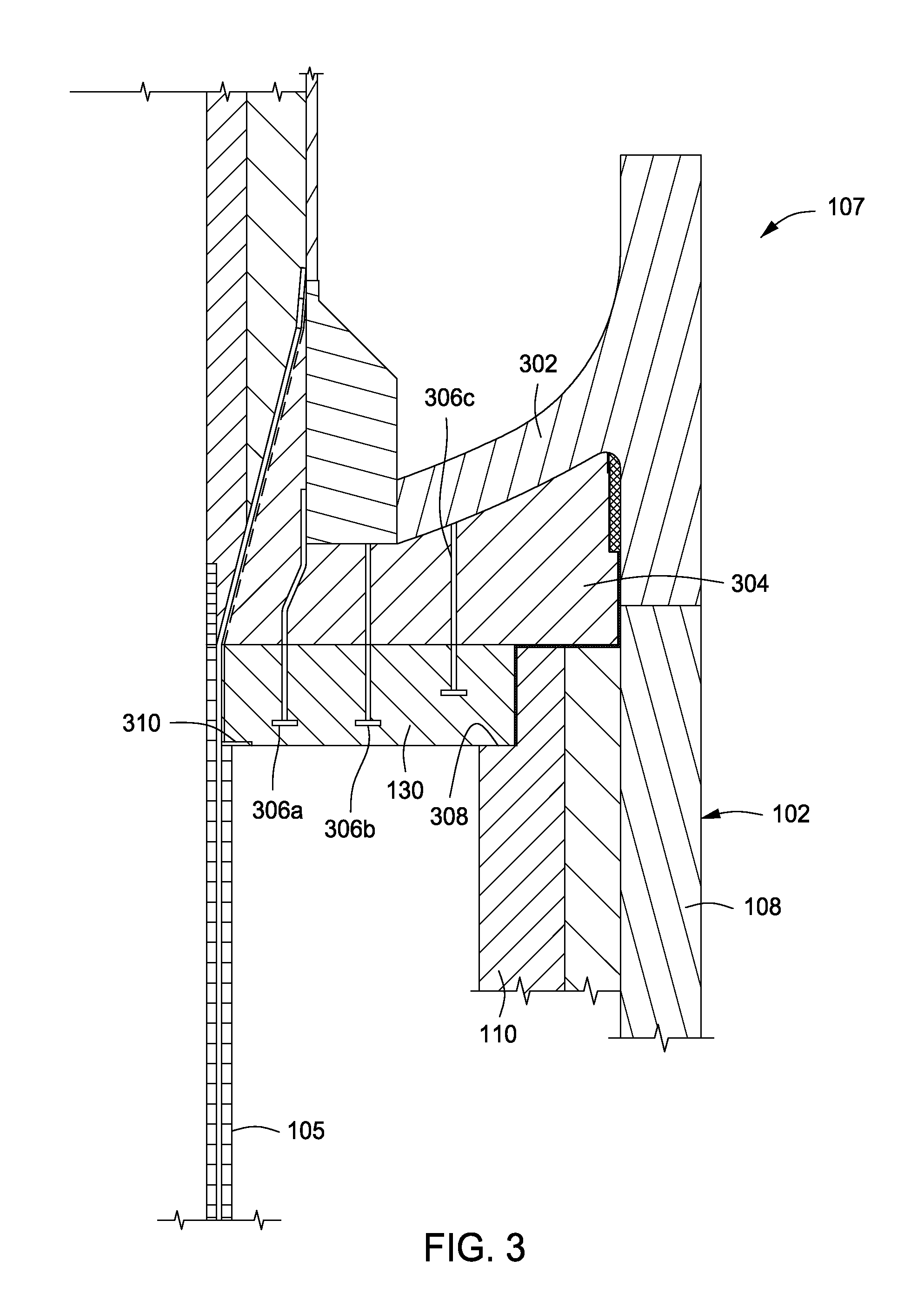
[0020]FIGS. 1 and 2 depict an exemplary cyclone 100, a...


PUM

PropertyMeasurementUnit
Pressureaaaaaaaaaa
Pressureaaaaaaaaaa
Internal pressureaaaaaaaaaa

Abstract

A pressure cyclone is disclosed having a concave top head, wherein the concave top head has a substantially flat roof disposed in the interior of the cyclone vessel. An inlet is tangentially-coupled to the vessel and has an inlet nozzle disposed therein and configured to smoothly transition into the cyclone vessel to create a vortex that separates solid particulates from an incoming particulate-fluid suspension. In particular, the one surface of the inlet nozzle is tangent to the inner surface of cyclone vessel and another surface of the inlet nozzle is parallel and continuous with the substantially flat roof. An inlet casing is disposed around a length of the inlet nozzle and configured to transition from a circular casing to an elliptical casing along the length of the inlet nozzle, and couple to the vessel with the elliptical casing.

Description

BACKGROUND OF THE INVENTION[0001]1. Field of the Invention[0002]Embodiments of the present invention generally relate to cyclonic separation units. More particularly, embodiments of the present invention relate to high-pressure cyclones having a concave, or inverted top head.[0003]2. Description of the Related Art[0004]Cyclonic separation involves separating a mixture of two or more phases, for example, fluid-particulate suspensions wherein one or more solid particulates are suspended in a carrier fluid, under a centrifugal force generated by centripetal motion. A cyclone separator is the mechanical device typically used to carry out cyclonic separation processes. In normal cyclone separator operation, a particulate suspension is introduced into the top of the cyclone separator via a tangential inlet where the solid particles tend to collect on the inner surface of the separator and its fluidic counterpart is entrained into a vortex. The solid particles gradually fall to the bottom ...

Claims


Application Information

Patent Timeline
IPC IPC(8): B04C5/04B04C5/081B01D45/12
CPCB01D45/12B04C5/081B04C5/04
Inventor PHILLIPS, WILLIAM E.
Owner KELLOGG BROWN & ROOT LLC
Why Eureka
Try Eureka