
Ventilator-Initiated Prompt Regarding Auto-PEEP Detection During Volume Ventilation Of Triggering Patient

a technology of auto-peep detection and ventilator, which is applied in the field of ventilator, can solve the problems of difficult diagnosis of auto-peep, many clinicians may not readily assess and evaluate the diverse ventilatorydata to detect certain patient conditions, and the complexity of modern ventilatory equipmen

Inactive Publication Date: 2011-11-10
TYCO HEALTHCARE GRP LP
View PDF4 Cites 121 Cited by
  • Summary
  • Abstract
  • Description
  • Claims
  • Application Information

AI Technical Summary

Problems solved by technology

As a result, modern ventilatory equipment has become increasingly complex, providing for detection and evaluation of a myriad of ventilatory parameters.
However, due to the shear magnitude of available ventilatory data, many clinicians may not readily assess and evaluate the diverse ventilatorydata to detect certain patient conditions and / or changes in patient condition.
Although quite serious, Auto-PEEP is difficult to diagnose because it is not easily recognized or detected by clinicians during the ventilation of a patient.
However, many clinicians may not easily identify or recognize data patterns and correlations indicative of certain patient conditions, changes in patient condition, and / or effectiveness of ventilatory treatment.
Further, clinicians may not readily determine appropriate ventilatory adjustments that may address certain patient conditions and / or the effectiveness of ventilatory treatment.
Specifically, clinicians may not readily detect or recognize the presence of Auto-PEEP during volume ventilation of a triggering patient.

Method used


Image

  • Ventilator-Initiated Prompt Regarding Auto-PEEP Detection During Volume Ventilation Of Triggering Patient
  • Ventilator-Initiated Prompt Regarding Auto-PEEP Detection During Volume Ventilation Of Triggering Patient
  • Ventilator-Initiated Prompt Regarding Auto-PEEP Detection During Volume Ventilation Of Triggering Patient

Examples


Embodiment Construction

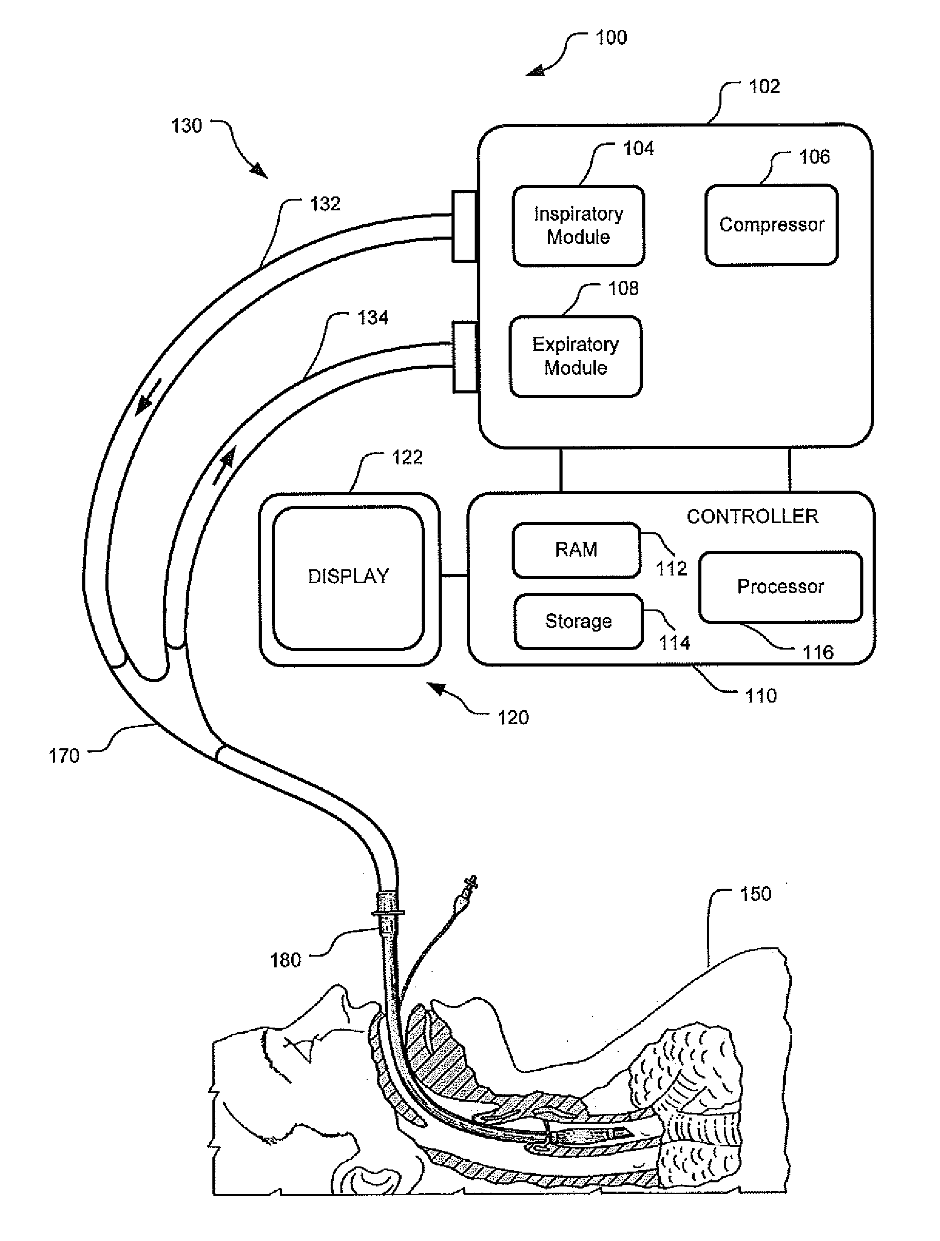
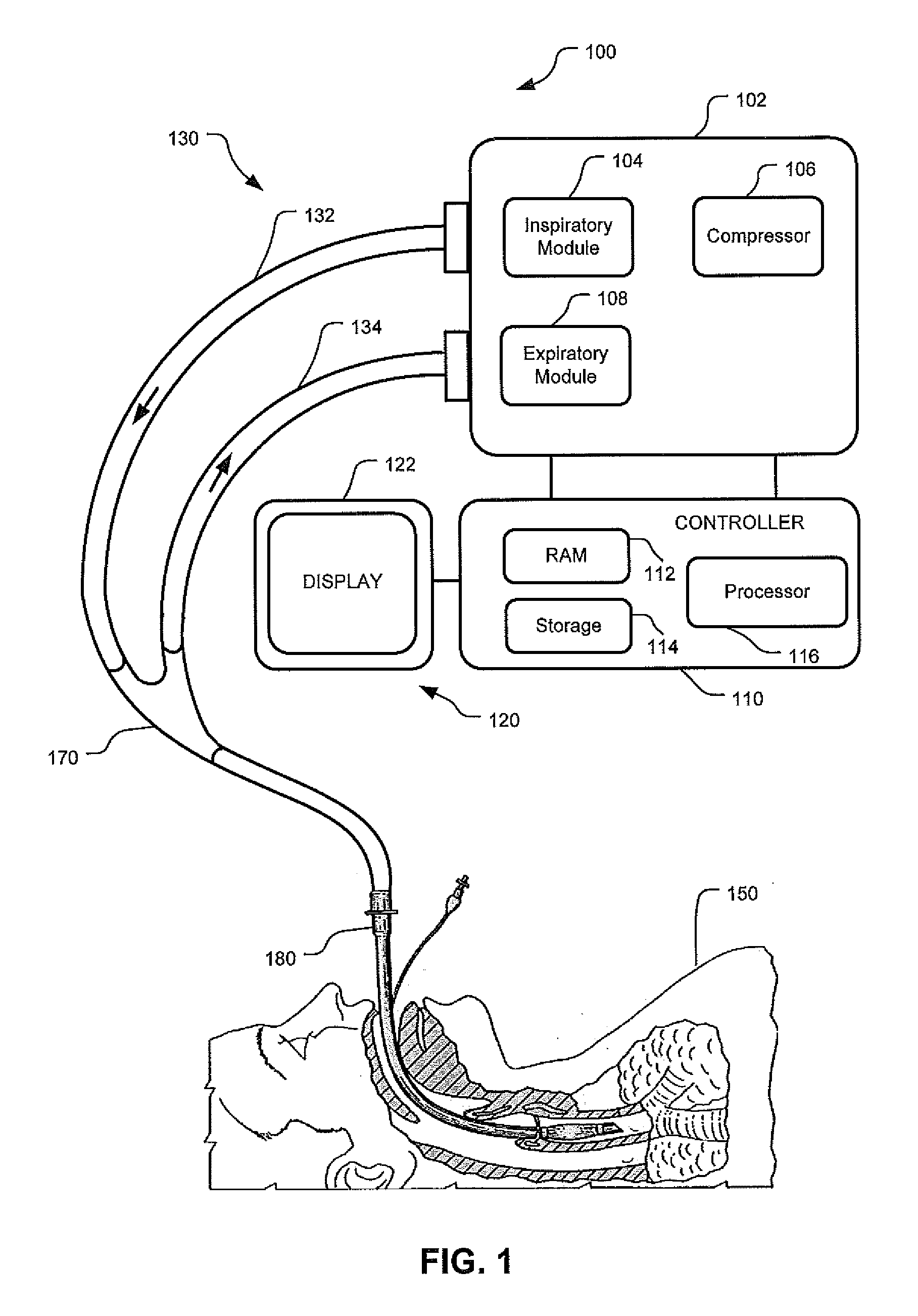
[0016]Although the techniques introduced above and discussed in detail below may be implemented for a variety of medical devices, the present disclosure will discuss the implementation of these techniques for use in a mechanical ventilator system. The reader will understand that the technology described in the context of a ventilator system could be adapted for use with other therapeutic equipment for alerting and advising clinicians regarding detected patient conditions.

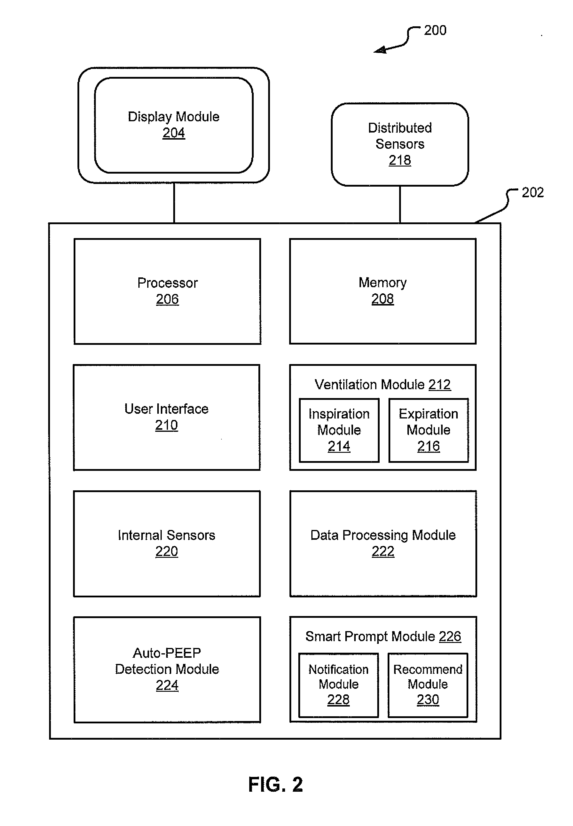
[0017]This disclosure describes systems and methods for monitoring and evaluating ventilatory parameters, analyzing ventilatory data associated with those parameters, and providing useful notifications and / or recommendations to clinicians. Modern ventilators monitor, evaluate, and graphically represent a myriad of ventilatory parameters. However, many clinicians may not easily identify or recognize data patterns and correlations indicative of certain patient conditions, changes in patient condition, and / or effective...


PUM


Abstract

This disclosure describes systems and methods for monitoring and evaluating ventilatory parameters, analyzing those parameters and providing useful notifications and recommendations to clinicians. That is, modern ventilators monitor, evaluate, and graphically represent a myriad of ventilatory parameters. However, many clinicians may not easily identify or recognize data patterns and correlations indicative of certain patient conditions, changes in patient condition, and / or effectiveness of ventilatory treatment. Further, clinicians may not readily determine appropriate ventilatory adjustments that may address certain patient conditions and / or the effectiveness of ventilatory treatment. Specifically, clinicians may not readily detect or recognize the presence of Auto-PEEP during volume ventilation of a triggering patient. According to embodiments, a ventilator may be configured to monitor and evaluate diverse ventilatory parameters to detect Auto-PEEP and may issue suitable notifications and recommendations to the clinician when Auto-PEEP is implicated. The suitable notifications and recommendations may further be provided in a hierarchical format.

Description

INTRODUCTION[0001]A ventilator is a device that mechanically helps patients breathe by replacing some or all of the muscular effort required to inflate and deflate the lungs. In recent years, there has been an accelerated trend towards an integrated clinical environment. That is, medical devices are becoming increasingly integrated with communication, computing, and control technologies. As a result, modern ventilatory equipment has become increasingly complex, providing for detection and evaluation of a myriad of ventilatory parameters. However, due to the shear magnitude of available ventilatory data, many clinicians may not readily assess and evaluate the diverse ventilatorydata to detect certain patient conditions and / or changes in patient condition. For example, Auto-PEEP is a dangerous condition associated with gas-trapping in the lungs that may be implicated by slight changes in a variety of different parameters. Although quite serious, Auto-PEEP is difficult to diagnose beca...

Claims


Application Information

Patent Timeline
IPC IPC(8): A61M16/00G06F3/048
CPCA61H31/005A61M16/0063A61M2016/0021A61M2016/0027A61M2016/0036A61M2205/502A61M2205/505A61M2205/584A61M2210/1014A61M2230/20A61M2230/43A61M2230/46G06F19/3406G06F19/345G06F19/3487A61M16/0051A61M16/0833A61M16/026G16H15/00G16H40/63G16H50/20
Inventor MILNE, GARYHENSLEY, KIRKDOYLE, PETER R.KIMM, GARDNER
Owner TYCO HEALTHCARE GRP LP
Learn More