
Silencer

Active Publication Date: 2011-11-10
PUREM GMBH
View PDF10 Cites 16 Cited by
  • Summary
  • Abstract
  • Description
  • Claims
  • Application Information

AI Technical Summary

Benefits of technology

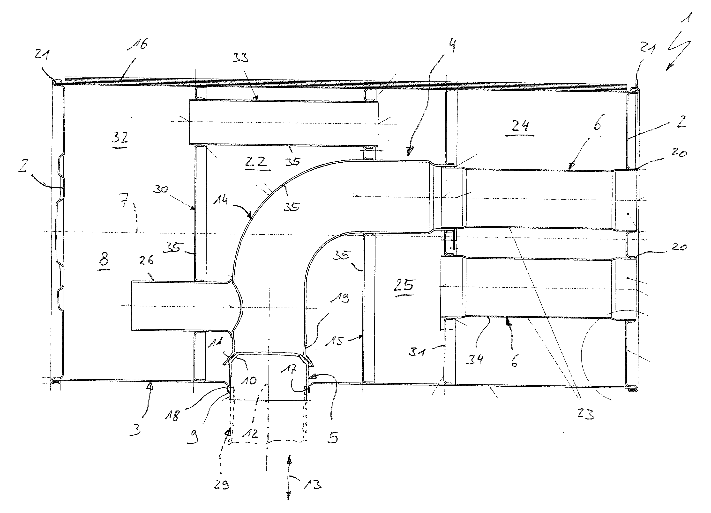
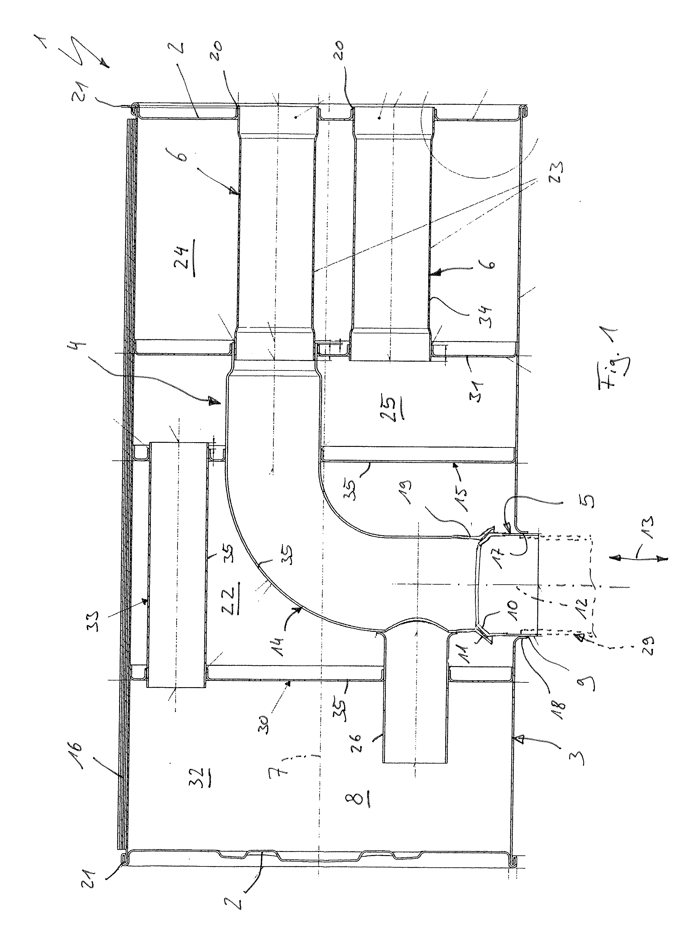
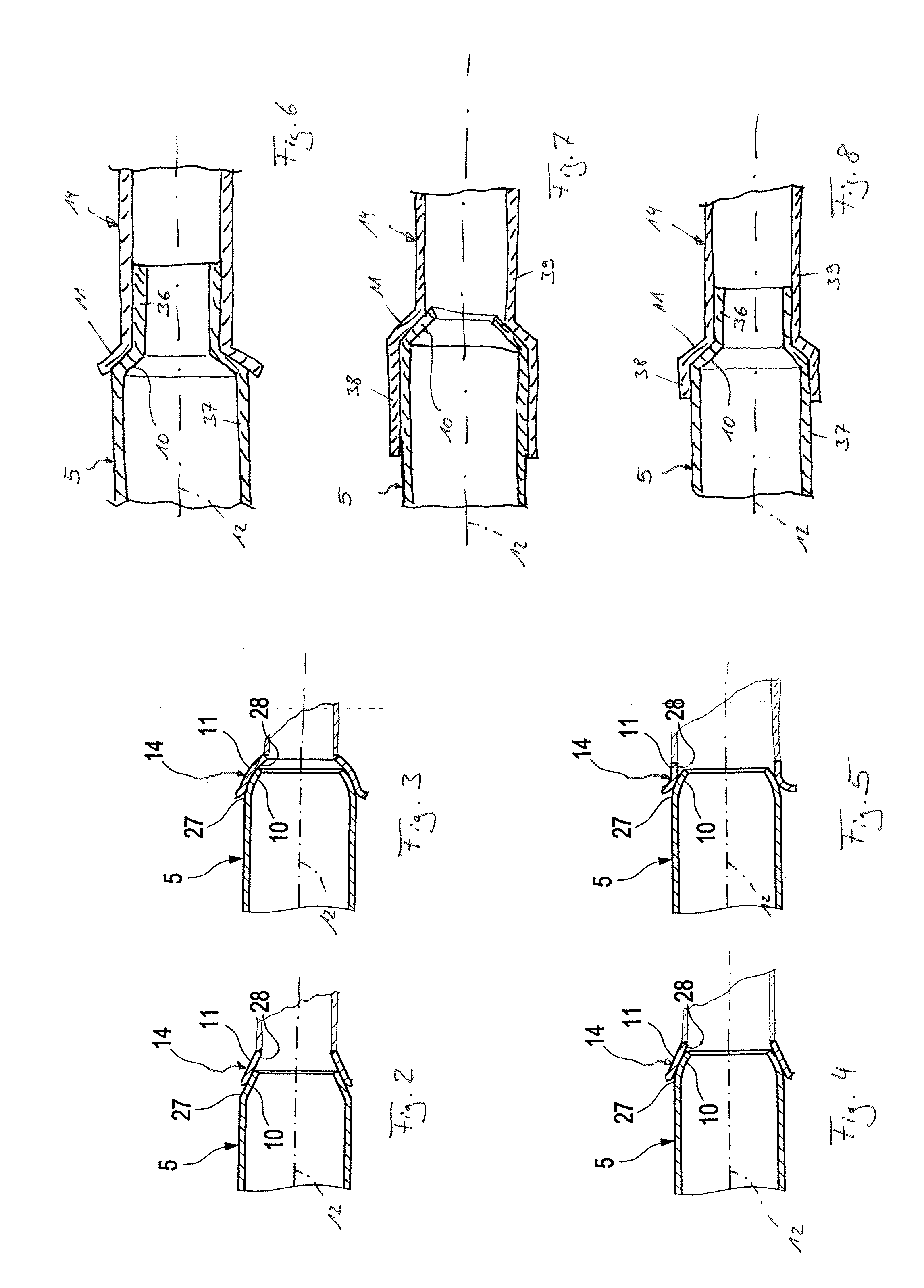
[0007]The invention is based on the general idea of equipping the pipe, which protrudes through the jacket into the silencer interior with a cone (a curved surface) at its end located inside, which in the assembled state interacts with a mating cone formed on the silencer insert for supporting the pipe on the silencer insert. Through the cone engaged with the mating cone a positive support between pipe and silencer insert materializes radially and axially to the axial direction of the pipe. Both the cone as well as the mating cone can be realized comparatively easily. The positive engagement between cone and mating cone during the assembly can be likewise produced easily. In the assembled state, an adequate support is obtained for the laterally attached pipe namely on the one hand on the jacket and on the other hand by way of the cone interacting with the mating cone, also on the silencer insert. Thus, an adequate stability for the laterally arranged pipe is achieved with cost-effective manufacturability. According to the invention, the mating cone is formed on an intermediate pipe of the silencer insert.
[0014]Additionally or alternatively it can be provided according to another embodiment that the cone comprises several slits arranged distributed in circumferential direction, which extend axially, which are axially open on one side and which in circumferential direction separate several cone segments from one another. Through this measure, the cone receives an increased radial spring elasticity in the region of its cone segments, which simplifies the insertion operation for the engagement between cone and mating cone. In addition or alternatively the mating cone can comprise several slits arranged distributed in circumferential direction which extend axially, which are axially open on one side and which in circumferential direction separate several mating cone segments from one another, as a result of which the mating cone possesses an increased radial spring elasticity in the region of the mating cone segments.

Problems solved by technology

This is problematic in connection with the wrap design since this laterally arranged pipe can only be assembled after the insertion of the silencer insert.
This supporting on the silencer insert however can only be realized with difficulty in connection with the wrap design because of the reduced accessibility.

Method used


Image

  • Silencer
  • Silencer
  • Silencer

Examples


Embodiment Construction

[0030]Referring to the drawings in particular, according to FIG. 1, a silencer 1 comprises two end face bottoms 2 facing away from each other, a closed circumferential jacket 3, at least one silencer insert 4, at least one inlet pipe 5 and at least one outlet pipe 6.

[0031]The silencer 1 is intended for installation in an exhaust system of a combustion engine which is not shown and can more preferably be used in a motor vehicle. Preferentially, the silencer 1 is a rear silencer, that is the silencer which, within the exhaust system or with respect to the exhaust gas flow direction, is the silencer through which the flow flows last before the exhaust gas reaches the respective tailpipe of the exhaust system which comprises the mouth of the exhaust system to the environment. Particularly advantageously the silencer is a silencer arranged positioned horizontally in the assembled state. With the transversely positioned silencer 1 an axial direction 7 of the silencer 1 substantially exten...


PUM

PropertyMeasurementUnit
Angleaaaaaaaaaa
Flow rateaaaaaaaaaa
Thermal propertiesaaaaaaaaaa

Abstract

A silencer for an exhaust system of a combustion engine, more preferably of a motor vehicle, has two end face bottoms facing away from each other, a closed circumferential jacket, at least one silencer insert, at least one inlet pipe and at least one outlet pipe. At least one of the pipes extends through the jacket into the silencer interior and is fastened to the jacket. The manufacture can be simplified if the pipe extending through the jacket has a cone, if the silencer insert on an intermediate pipe has a mating cone which engages in the cone.

Description

CROSS REFERENCE TO RELATED APPLICATIONS[0001]This application claims the benefit of priority under 35 U.S.C. §119 of German Patent Application DE 10 2010 019959.1 filed May 8, 2010, the entire contents of which are incorporated herein by reference.FIELD OF THE INVENTION[0002]The present invention relates to a silencer (also known as a muffler) for an exhaust system of a combustion engine, more preferably of a motor vehicle, with two end face bottoms facing away from each other, with a closed circumferential jacket, with at least one silencer insert, with at least one inlet pipe and with at least one outlet pipe. In addition, the invention relates to an associated manufacturing method.BACKGROUND OF THE INVENTION[0003]Silencers (mufflers) are divided into two manufacturing types with respect to the manufacture of their closed circumferential jacket, namely silencers in shell design and silencers in wrap design. While with the shell design two deep-drawn metal sheets are joined togethe...

Claims


Application Information

Patent Timeline
IPC IPC(8): F01N13/08B23P11/00
CPCF01N1/08F01N13/1844Y10T29/49398F01N2470/18Y10T29/49826F01N2450/00F01N1/023
Inventor TAUSCHEK, THOMASSPIETH, ARNULFWIRTH, GEORGE
Owner PUREM GMBH
Learn More