
Systems and Methods for Transmission of Trigger-Based Alarm Indication Suppression Messages

Inactive Publication Date: 2011-11-17
FUJITSU LTD
View PDF3 Cites 6 Cited by
  • Summary
  • Abstract
  • Description
  • Claims
  • Application Information

AI Technical Summary

Benefits of technology

[0005]In accordance with the present invention, disadvantages and problems associated w

Problems solved by technology

One disadvantage of the traditional transmission of Eth-AIS messages in such architectures is that Eth-AIS messages must traverse the entire switch fabric of the network element in the case of a down (e.g., failed or non-operational) MEP.
Such approa

Method used


Image

  • Systems and Methods for Transmission of Trigger-Based Alarm Indication Suppression Messages
  • Systems and Methods for Transmission of Trigger-Based Alarm Indication Suppression Messages
  • Systems and Methods for Transmission of Trigger-Based Alarm Indication Suppression Messages

Examples


Example

DETAILED DESCRIPTION OF THE DRAWINGS

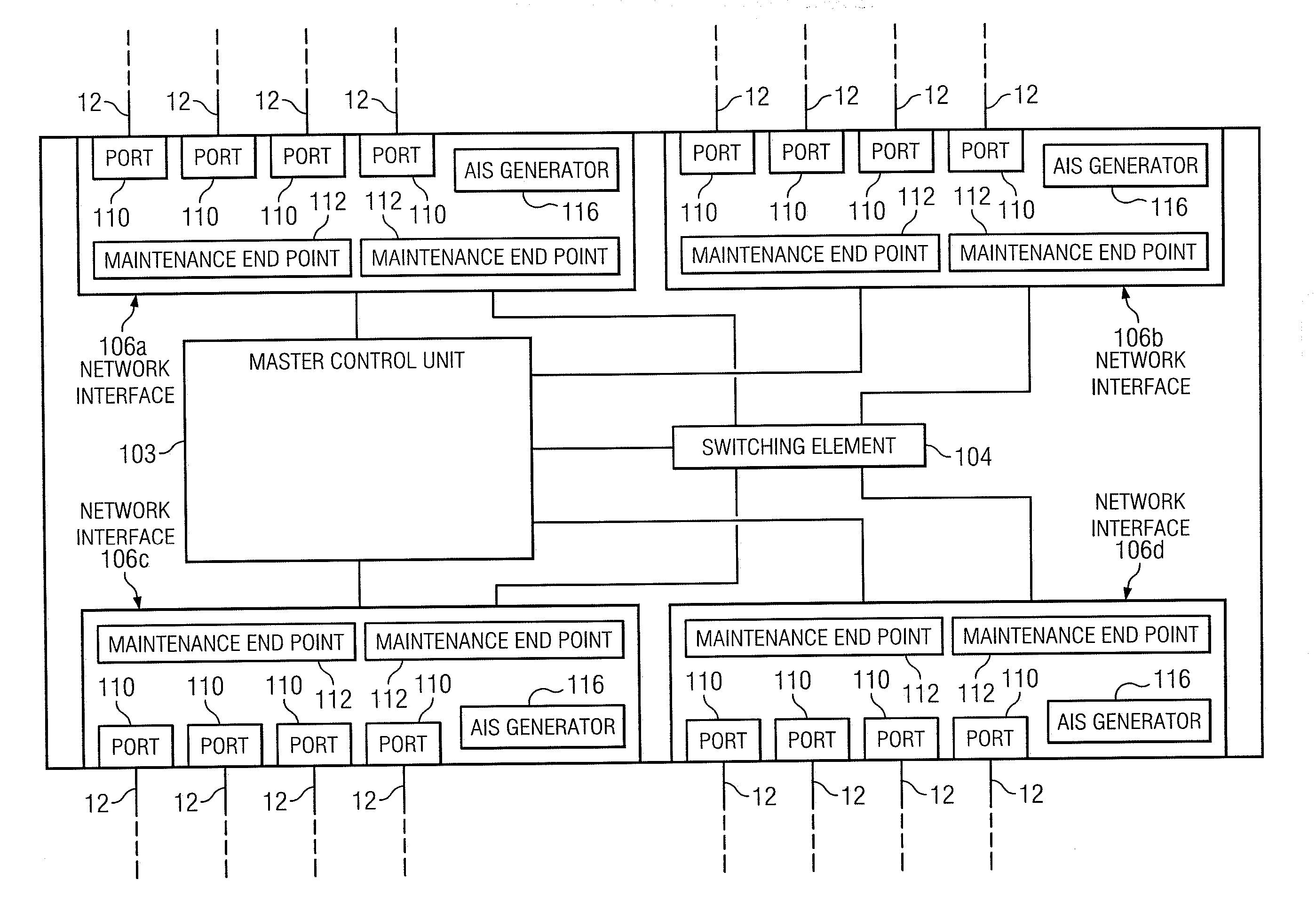
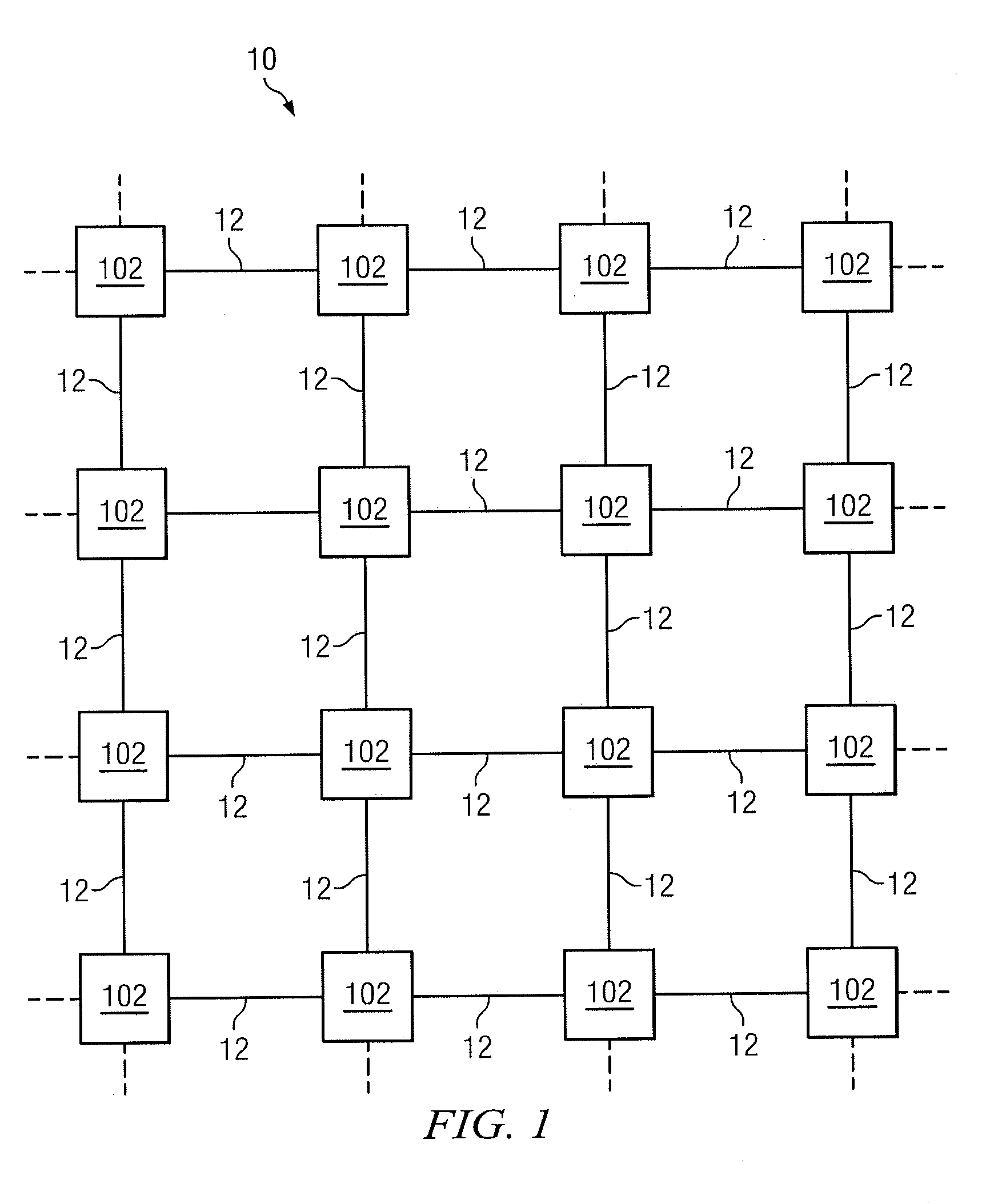
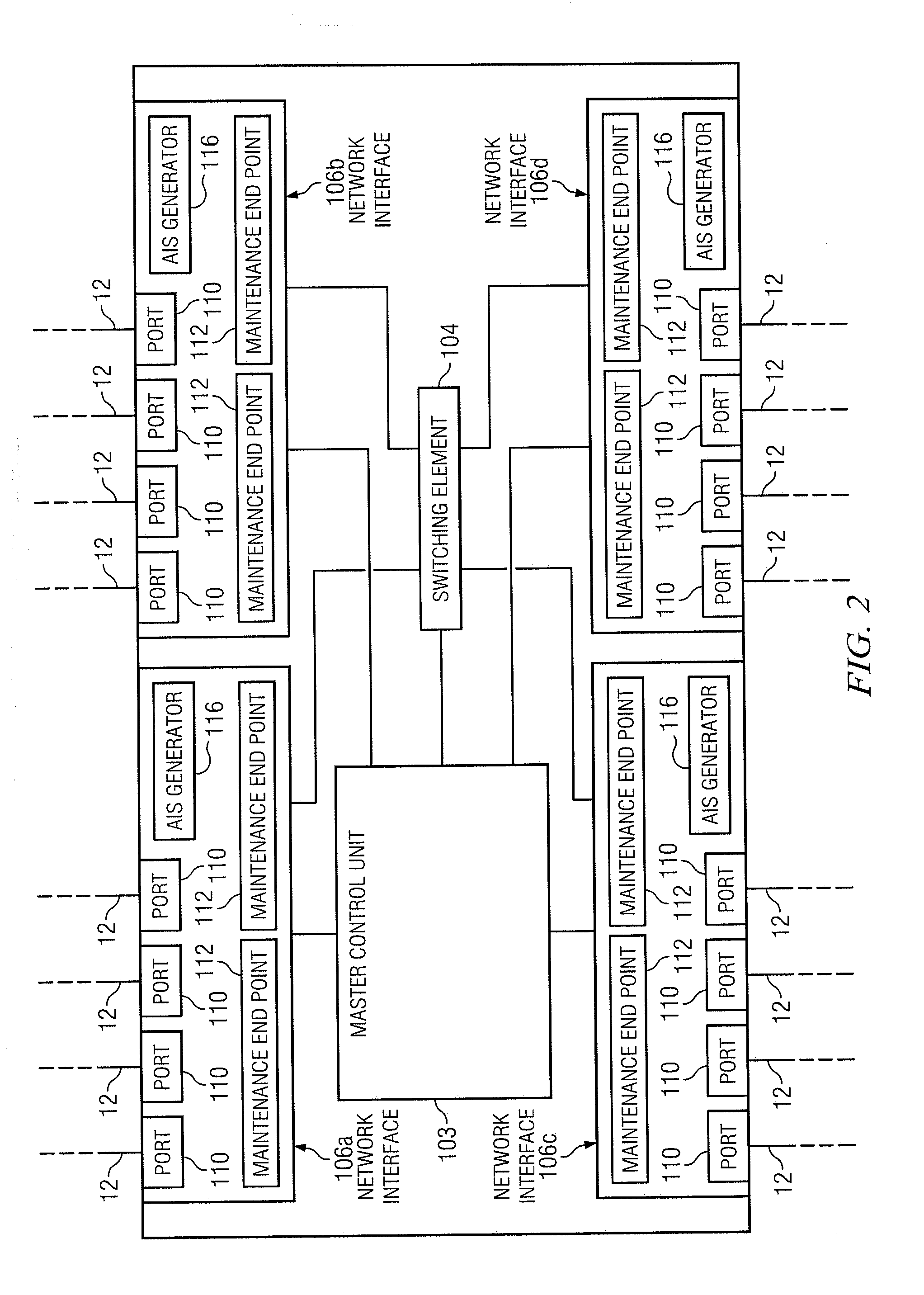
[0012]Embodiments of the present invention and its advantages are best understood by referring to FIGS. 1-2, like numerals being used for like and corresponding parts of the various drawings.

[0013]FIG. 1 illustrates a block diagram of an example network 10, in accordance with certain embodiments of the present disclosure. In certain embodiments, network 10 may be an Ethernet network. Network 10 may include one or more transmission media 12 operable to transport one or more signals communicated by components of network 10. The components of network 10, coupled together by transmission media 12, may include a plurality of network elements 102. In the illustrated network 10, each network element 102 is coupled to four other nodes. However, any suitable configuration of any suitable number of network elements 102 may create network 10. Although network 10 is shown as a mesh network, network 10 may also be configured as a ring network, a point-to-point...


PUM


Abstract

According to one embodiment, a method may include communicating an alarm suppression indication trigger message from a maintenance end point to an alarm indication suppression generator. The method may further include communicating, by the alarm indication suppression generator in response to receiving the alarm indication trigger message, an alarm indication suppression message to at least one flow point that has alarm indication suppression enabled for the maintenance end point such that the alarm indication suppression message is received by at least one other maintenance end point upstream of the maintenance end point.

Description

TECHNICAL FIELD[0001]This invention relates generally to the field of communications systems and more specifically to transmission of alarm indication suppression messages.BACKGROUND[0002]A communication network may include network elements that route packets through the network. Some network elements may include a distributed architecture, wherein packet processing may be distributed among several subsystems of the network element (e.g., line cards).[0003]Service Operation, Administration, and Management (“Service OAM” or “SOAM”), is defined by IEEE 802.1ag and defines Maintenance Entity Group End Points (MEPs) that reside on a line card. MEPs may include service-aware MEPs (e.g., MEPs attached to a service point or flow point) and service-transparent MEPs (e.g., MEPs that are not placed on a service flow point, but rather at a service aggregation point, such as an interface level). The ITU Y.1731 standard complements IEEE 802.1ag by allowing a MEP to transmit a Ethernet Alarm Indi...

Claims


Application Information

Patent Timeline
IPC IPC(8): G08B23/00
CPCH04L41/0627
Inventor UNGER, STEPHEN JOHNHAAS, DAVID JOSEPHMU, JIAN-LINVLADESCU, VIRGILYASEEN, NIMERMENASINAHAL, BASAVARAJWAN, CALVIN
Owner FUJITSU LTD
Learn More