Method and apparatus for cache control

a cache and memory technology, applied in the field of processors, can solve the problem that the larger cache memory may consume more power than the smaller one, and achieve the effect of reducing the power consumption of the smaller cache memory

Active Publication Date: 2011-11-17
ADVANCED MICRO DEVICES INC
View PDF22 Cites 132 Cited by
  • Summary
  • Abstract
  • Description
  • Claims
  • Application Information

AI Technical Summary

Problems solved by technology

However, these larger cache memories may consume more power than their smaller counterparts.

Method used


Image

  • Method and apparatus for cache control
  • Method and apparatus for cache control
  • Method and apparatus for cache control

Examples


Embodiment Construction

Overview of Processor Embodiments

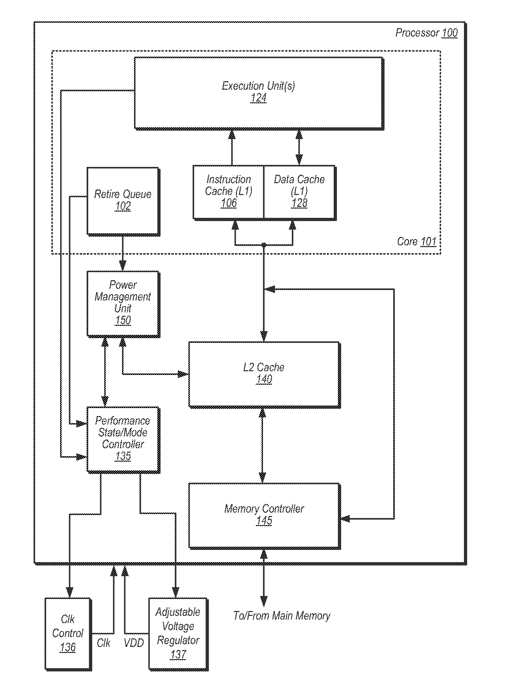
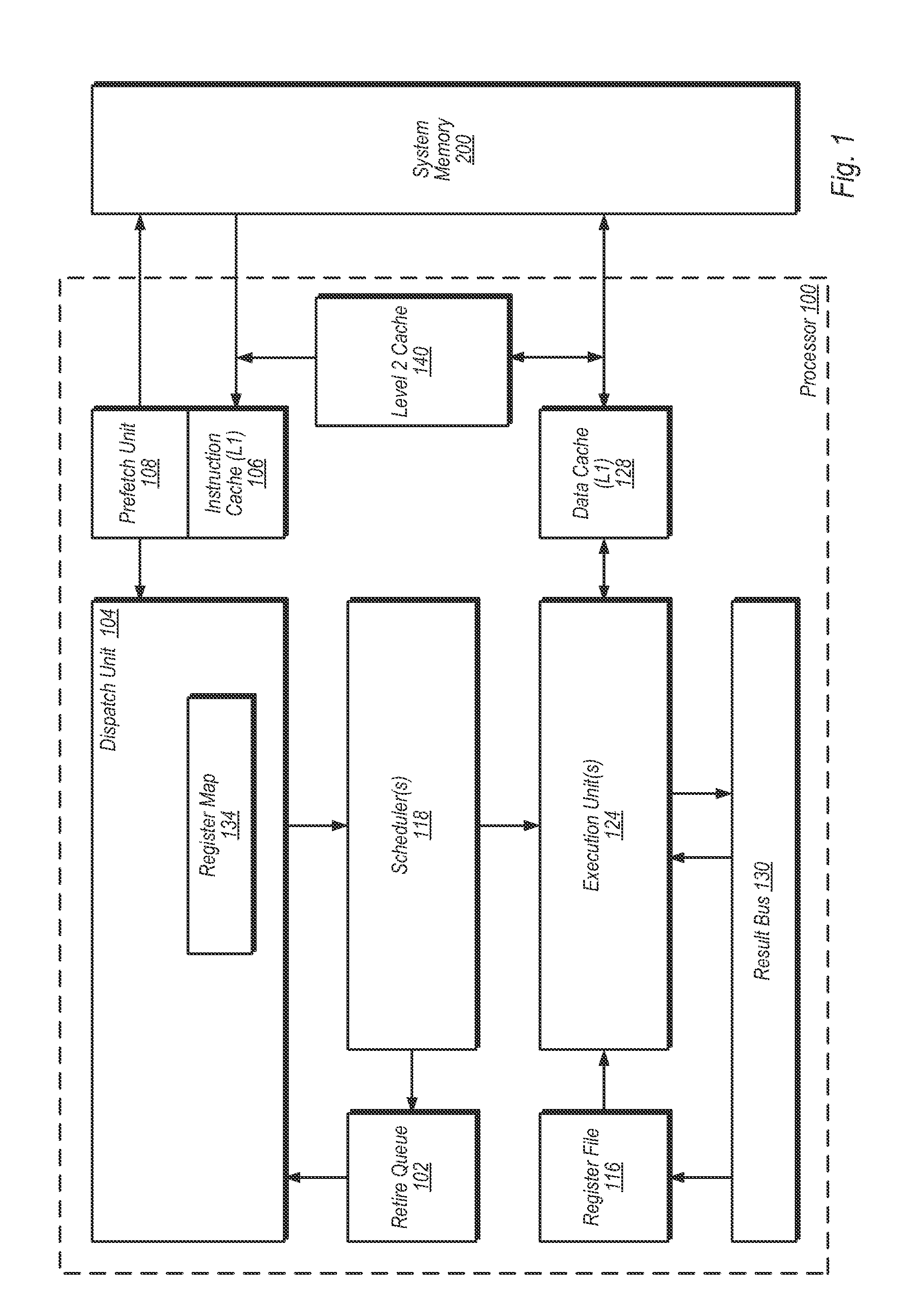
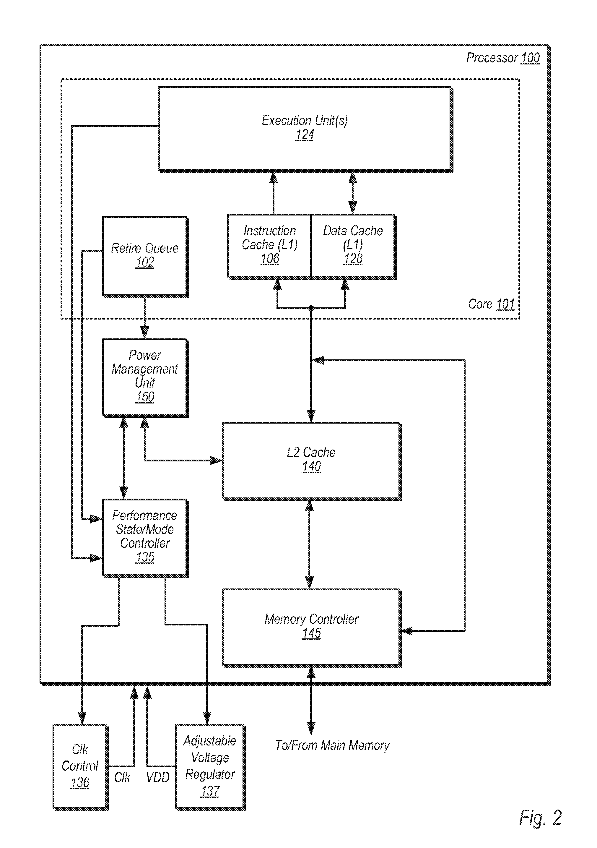
[0022]FIG. 1 is a block diagram of one embodiment of a processor 100. The processor 100 is configured to execute instructions stored in a system memory 200. Many of these instructions operate on data stored in the system memory 200. It is noted that the system memory 200 may be physically distributed throughout a computer system and / or may be accessed by one or more processors 100.

[0023]In the illustrated embodiment, the processor 100 may include a level one (L1) instruction cache 106 and an L1 data cache 128. The processor 100 may include a prefetch unit 108 coupled to the instruction cache 106. A dispatch unit 104 may be configured to receive instructions from the instruction cache 106 and to dispatch operations to the scheduler(s) 118. One or more of the schedulers 118 may be coupled to receive dispatched operations from the dispatch unit 104 and to issue operations to the one or more execution unit(s) 124. The execution unit(s) 124 may include on...


PUM


Abstract

A method and apparatus for dynamically controlling a cache size is disclosed. In one embodiment, a method includes changing an operating point of a processor from a first operating point to a second operating point, and selectively removing power from one or more ways of a cache memory responsive to changing the operating point. The method further includes processing one or more instructions in the processor subsequent to removing power from the one or more ways of the cache memory, wherein said processing includes accessing one or more ways of the cache memory from which power was not removed.

Description

BACKGROUND[0001]1. Field of the Invention[0002]This invention relates to processors, and more particularly, to cache memories in processors.[0003]2. Description of the Related Art[0004]Cache memories figure prominently in the performance of computer system processors. As processor technology has advanced and the demand for performance has increased, the number and capacity of cache memories has followed. Some processors may have a single cache or single level of cache memory, while others may have multiple levels of caches. Some cache memories may be used for storing data, while other cache memories may be used for storing instructions, while some may store both. Cache memories for storing other types of information (e.g., address translations) are also used in some processors.[0005]Cache memories may be defined by levels, based on their proximity to execution units of a processor core. For example, a level one (L1) cache may be the closest cache to the execution unit(s), a level tw...

Claims


Application Information

Patent Timeline
Patent Type & Authority Applications(United States)
IPC IPC(8): G06F1/32G06F12/08
CPCG06F1/3203G06F1/324G06F1/3275G06F1/3296Y02B60/1228G06F2212/1028Y02B60/1225Y02B60/1217Y02B60/1285G06F12/0864Y02D10/00G06F1/32G06F9/06G06F12/08
Inventor BRANOVER, ALEXANDERHACK, NORMAN M.STEINMAN, MAURICE B.KALAMATIANOS, JOHNOWEN, JONATHAN M.
Owner ADVANCED MICRO DEVICES INC
Why Eureka
Try Eureka