Apparatus and method for allocating channel state information-reference signal in wireless communication system

a wireless communication system and information reference signal technology, applied in the field of wireless communication system technology, can solve the problems of insufficient channel information detection with current crss defined for four existing antennas, and no discussion about a scheme for allocating csi-rss to each antenna por

Active Publication Date: 2011-12-01
PANTECH CORP
View PDF4 Cites 74 Cited by
  • Summary
  • Abstract
  • Description
  • Claims
  • Application Information

AI Technical Summary

Problems solved by technology

Therefore, the current CRSs defined for four existing antennas are insufficient for detection of channel information at the time of downlink transmission.
However, methods for allocating corresponding CSI-RS patterns to resource areas by each antenna port in each eNB (or eNodeB) or cell have not been specifically arranged yet.
However, there has been no discussion about a scheme for allocating CSI-RSs to each antenna port in such a case.

Method used


Image

  • Apparatus and method for allocating channel state information-reference signal in wireless communication system
  • Apparatus and method for allocating channel state information-reference signal in wireless communication system
  • Apparatus and method for allocating channel state information-reference signal in wireless communication system

Examples


first embodiment

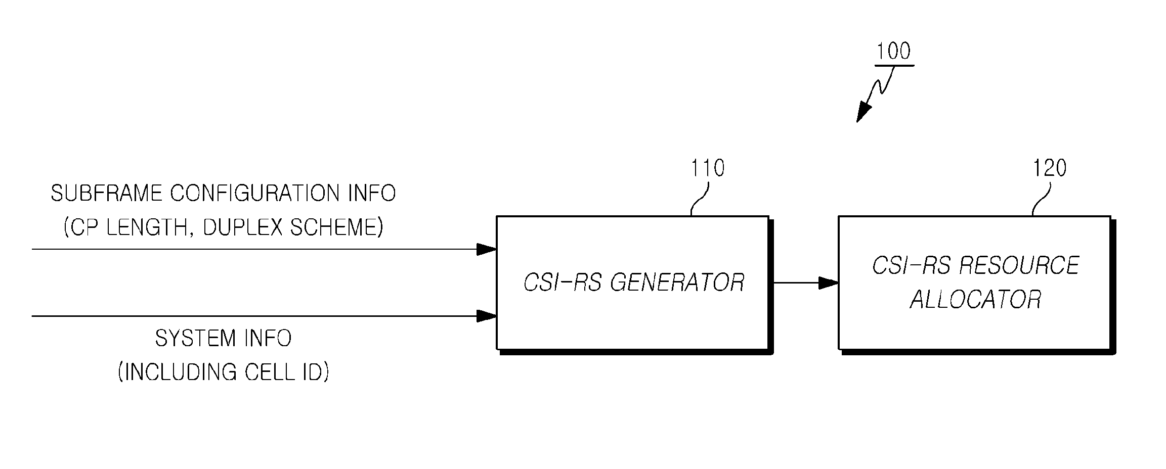
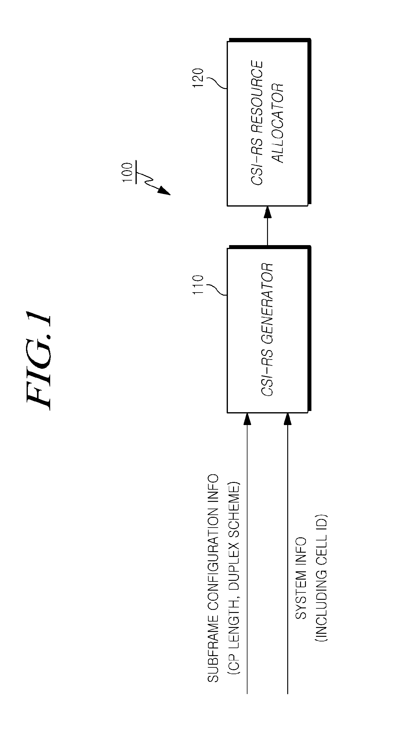
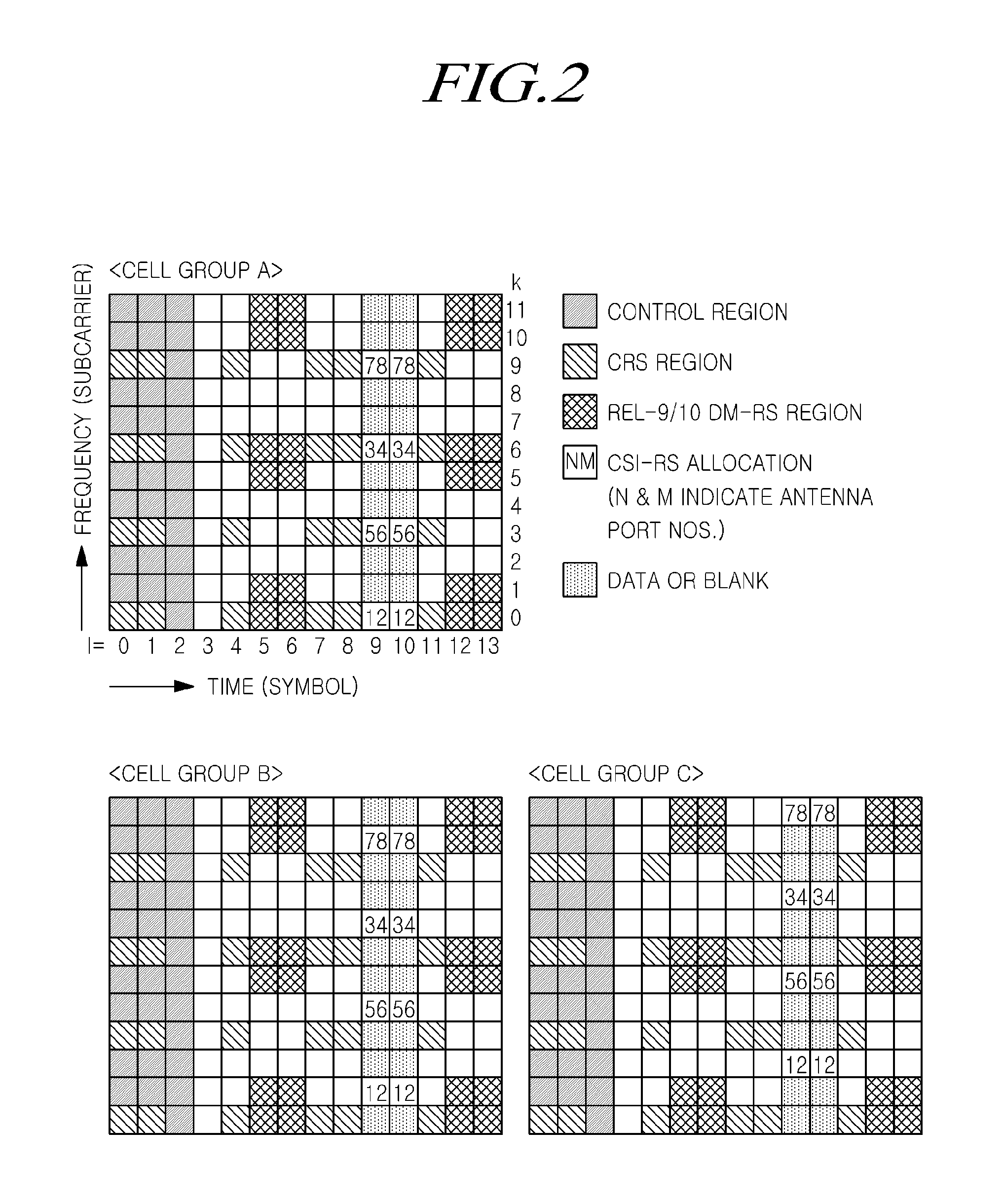
[0090]FIG. 2 shows a CSI-RS allocation scheme according to the present invention, for a downlink subframe in which the CP is a normal CP and the duplex scheme is FDD or TDD.

[0091]Further, in the first embodiment of the present invention as shown in FIG. 2, a duplicated allocation of AP5 is allowed (that is, CSI-RS allocation to the location of AP5 is allowed), without consideration on whether to use AP2 or AP3 (that is, it is the same regardless of either if AP2 or AP3 is used or if AP2 or AP3 is not used).

[0092]The following configuration is applied to the first embodiment of the present invention.[0093]Two consecutive OFDM symbols are used, which may include the 10th and the 11th symbols (i.e. l=9 and 10).[0094]Every two antenna ports are tied into one pair, and pairs are multiplexed by FDM while two consecutive OFDM symbols for two antenna ports within each pair are multiplexed by CDM (i.e. CDM-T) by using an orthogonal code such as the Orthogonal Cove Code (OCC).

[0095]In the pre...

second embodiment

[0109]In the present invention, whether to use AP2 or AP3 is not considered (that is, it is the same regardless of either if AP2 or AP3 is used or if AP2 or AP3 is not used).

[0110]The following configuration is applied to the second embodiment of the present invention.[0111]Two consecutive OFDM symbols are used, and the CSI-RSs are allocated to two different consecutive symbol axes according to the cell.[0112]It is the same as in the first embodiment of the present invention shown in FIG. 2 in view of that an antenna port is identified by an OCC code and the CSI-RSs are allocated to REs corresponding to one half of the number of antenna ports for each symbol in the second embodiment of the present invention.[0113]For a total of three basic cell groups, CSI-RSs may be configured. In the first cell group, CSI-RSs are allocated to the 10th and 11th symbol axes and to the other REs except for the REs, at which AP5 is located, in the 10th and 11th symbol axes. In the second cell group, C...

third embodiment

[0120]FIG. 4 shows a CSI-RS allocation scheme according to the present invention, for a subframe in which the CP is a normal CP, the duplex scheme is TDD, and the number of OFDM symbols allocated to the downlink (DwPTS) within the subframe is 11 or 12. In this event, the subframe may be the special subframe in TDD as described above.

[0121]Further, in the third embodiment of the present invention, duplicated allocation of AP5 is allowed, and whether to use AP2 or AP3 is not considered.

[0122]The following configuration is applied to the third embodiment of the present invention shown in FIG. 4.[0123]Two consecutive OFDM symbols are used, which may include the 6th and the 7th symbols (i.e. l=5 and 6).[0124]It is the same as in the first embodiment of the present invention shown in FIG. 2 in view of that an antenna port is identified by an OCC code and the CSI-RSs are allocated to REs corresponding to one half of the number of antenna ports for each symbol in the second embodiment of th...


PUM


Abstract

Embodiments of the present invention relate to a wireless communication system, and more particularly, to a technology for allocating a Channel State Information-Reference Signal (CSI-RS) in a wireless communication system.Embodiments of the present invention provides an apparatus and method for allocating CSI-RSs to resource areas, in which, under the condition of a subframe in which the CP is an extended CP, and the duplex scheme is TDD, if CSI-RSs for maximum 8 antenna ports are allocated, the CSI-RSs are allocated to the 8th and 9th symbols (symbol No. l=7 and 8), wherein each CSI-RS for every two antenna ports is allocated to the same RE while being discriminated from each other by an orthogonal code and neighbor CSI-RS allocated REs in the frequency axis are spaced by an interval of three REs.

Description

CROSS-REFERENCE TO RELATED APPLICATIONS[0001]This application claims priority from and the benefit under 35 U.S.C. §119(a) of Korean Patent Application No. 10-2010-0052033 filed on Jun. 1, 2010 and Korean Patent Application No. 10-2010-0055073 filed on Jun. 10, 2010, both of which are hereby incorporated by reference for all purposes as if fully set forth herein.BACKGROUND[0002]1. Field[0003]Embodiments of the present invention relate to a wireless communication system, and more particularly, to a technology for allocating a Channel State Information-Reference Signal (CSI-RS) in a wireless communication system.[0004]2. Discussion of the Background[0005]With the development of communication systems, a wide variety of wireless terminals are being used by consumers, such as business companies and individuals.[0006]Mobile communication systems, such as 3GPP (3rd Generation Partnership Project) including LTE (Long Term Evolution) and LTE-A (LTE Advanced), allow for the development of tec...

Claims


Application Information

Patent Timeline
Patent Type & Authority Applications(United States)
IPC IPC(8): H04J3/00
CPCH04L5/0007H04L5/005H04L5/0039H04L5/0048H04L5/0026H04L5/0057H04L5/0073H04L5/1469H04L25/0226H04L5/0082H04L2025/03426H04L2025/03802H04B7/0413H04B7/0626H04L5/14H04L27/2607
Inventor YOON, SUNGJUNPARK, KYOUNG-MINKIM, KITAE
Owner PANTECH CORP
Why Eureka
Try Eureka