Method for the production of a fastening element for dry construction elements

a technology of fastening elements and construction elements, which is applied in the direction of girders, mechanical devices, walls, etc., can solve the problems of not always easy to precisely position screws and not lead to optimal handling of fastening elements, and achieve the effect of being mounted especially easily

Active Publication Date: 2011-12-08
RICHTER SYST
View PDF0 Cites 4 Cited by
  • Summary
  • Abstract
  • Description
  • Claims
  • Application Information

AI Technical Summary

Benefits of technology

[0008]Therefore, an objective of the present invention provides a fastening element for dry construction elements that can be mounted especially easily, as well as a method for the production of such a fastening element.
[0010]The sliding surfaces allow an especially simple affixation of the fastening element. If screws are used for this purpose then, thanks to the effect of the sliding surfaces, they can slide into the next depression and be screwed in there. In this manner, the screws can always be inserted at precisely defined positions without this calling for any extra effort.
[0011]Screws can be inserted especially easily if the sliding surfaces each have an inclination angle of more than 5°, especially more than 7°, relative to the imaginary center line of the sheet metal material.
[0013]According to the invention, it has proven to be especially advantageous for the center point distance between the individual depressions to range between three times and ten times the thickness of the sheet metal material, especially between four times and six times the thickness of the sheet metal material. The term ‘thickness’ here refers to the thickness of the sheet metal material itself, that is to say, without taking depressions and elevations into account. In this context, it is achieved at the same time that the fastening element is easy to mount and has high stability values.
[0015]High stability, along with easy mounting, are also promoted by the fact that the elevations have a height that is between 0.8 times and 1.4 times the thickness of the sheet metal material, measured from the imaginary center line of the sheet metal material, and / or in by the fact that the depressions have a depth between 0.3 times and 2.0 times, especially between 0.3 times and 1.0 time the thickness of the sheet metal material, measured from the outer enveloping surface of the sheet metal material. The outer enveloping surface is formed by the highest points of the elevations.
[0020]Since the top roller and / or the bottom roller has a plurality of toothed disks arranged next to each other, depressions and elevations can be created in several rows next to each other. Such top rollers and bottom rollers are also very easy and cheap to produce since the individual toothed disks can be processed separately and are only joined at the end to form the top rollers and bottom rollers.

Problems solved by technology

If the fastening element is configured to be flat at the screwing site, it is not always easy to precisely position the screws, since the screws can slip away when they are being screwed in, which is normally done with a battery-operated screwdriver.
The provision of a corrugated area alone as is known from the state of the art, however, would not lead to optimal handling of the fastening element.

Method used


Image

  • Method for the production of a fastening element for dry construction elements
  • Method for the production of a fastening element for dry construction elements
  • Method for the production of a fastening element for dry construction elements

Examples


Embodiment Construction

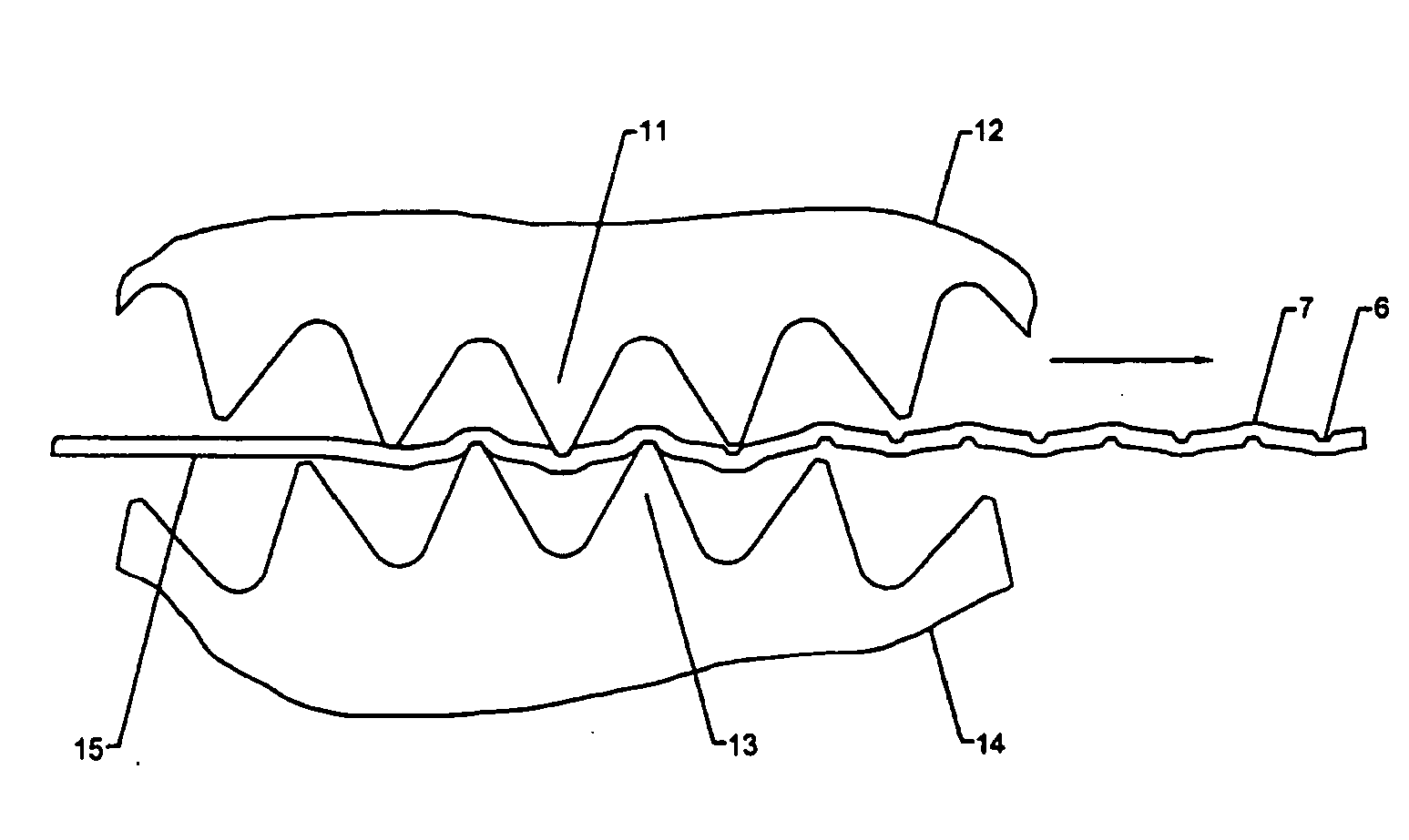
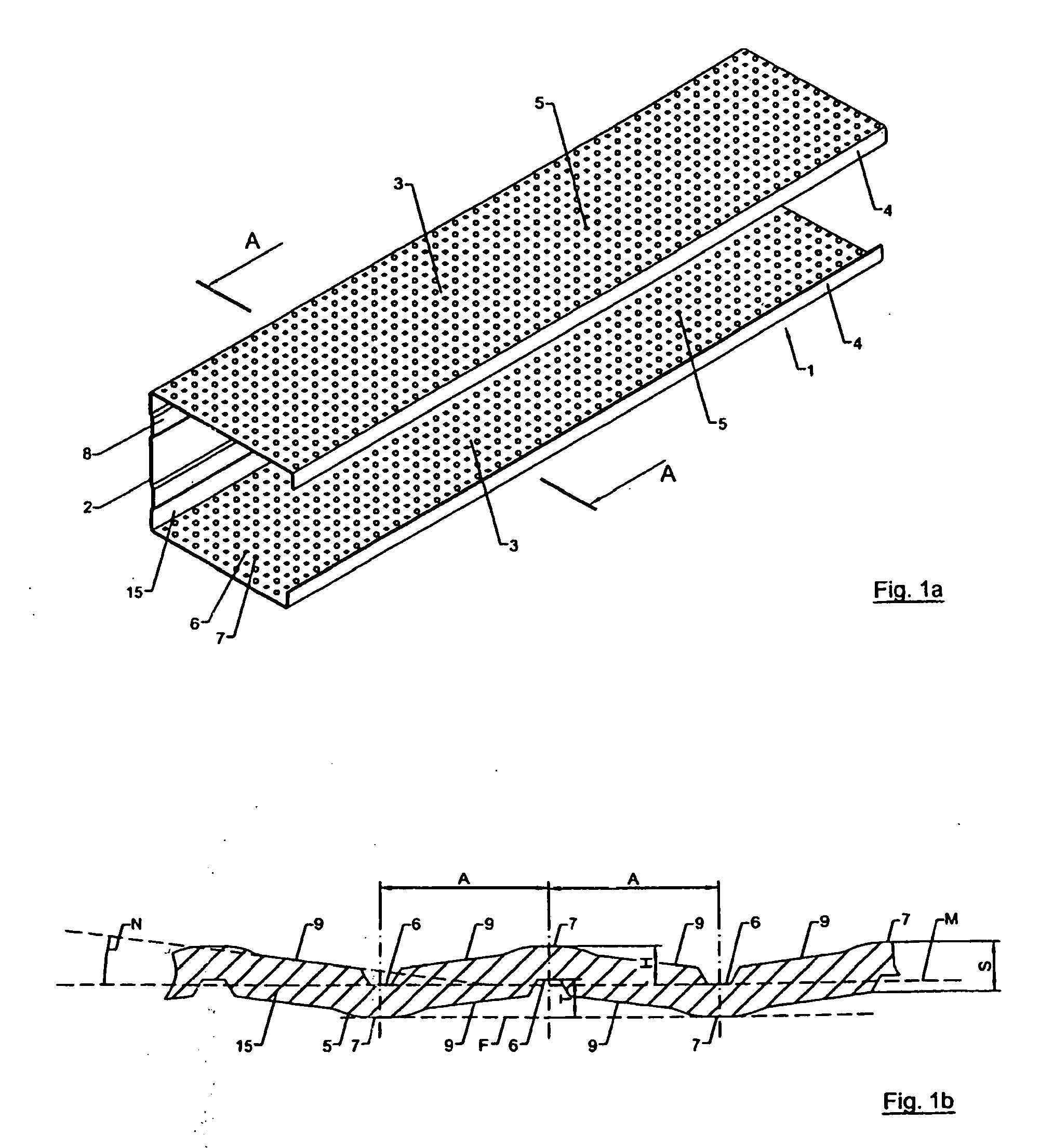
[0040]FIGS. 1a, 2 and 3 each show a fastening element 1, 1′, 1″ for dry construction elements. The fastening elements 1, 1′, 1″ are each made of a profiled sheet metal material having a bottom section 2 at whose ends bent leg sections 3 are provided. The leg sections 3, each of which forms a fastening flange, extend essentially perpendicular to the bottom section 2.

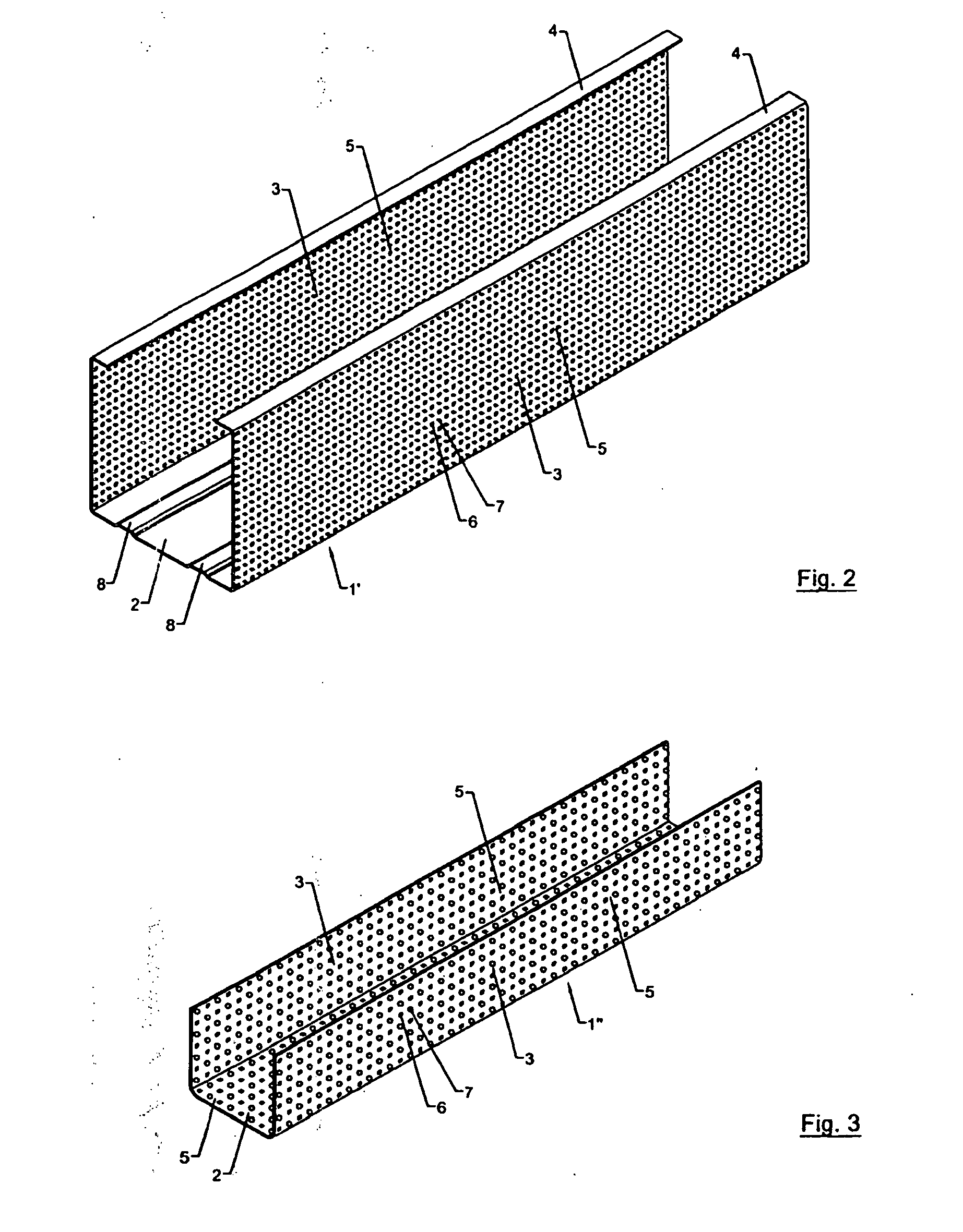
[0041]In the embodiments shown in FIGS. 1a and 2, each of the outer ends of the leg sections 3 has bent strips 4 that face inwards and that form support edges. Such fastening elements 1, 1′ are also referred to as C-sections.

[0042]The fastening element 1″ shown in FIG. 3, which does not have a bent strip at the outer ends of the leg sections 3, is a so-called U-section.

[0043]The described fastening elements 1, 1′, 1″ can be employed in dry construction as support structures, for example, for building partitions, suspended ceilings, etc.

[0044]The fastening elements 1, 1′, 1″ shown are made of metal, especially of galvanize...


PUM

PropertyMeasurementUnit
inclination angle Naaaaaaaaaa
lengthaaaaaaaaaa

Abstract

A method for the production of a fastening element for dry construction elements involving feeding a flat sheet metal material through a nip formed between a top roller having first teeth and a bottom roller having second teeth, in order to create depressions and elevations as well as slanted sliding surfaces.

Description

CROSS REFERENCE TO RELATED APPLICATIONS[0001]This is a divisional application of U.S. patent application Ser. No. 12 / 291,152, filed on Nov. 6, 2008, which claims priority to German patent application No. DE 10 2006 021 556.7 filed on May 8, 2006, through PCT / EP2007 / 003902 filed on May 3, 2007, hereby incorporated by reference herein.BACKGROUND OF THE INVENTION[0002]The present invention relates to a fastening element for dry construction elements and to a method for the production of such a fastening element.[0003]Swiss patent specification CH 486 281 describes a corrugated panel made of metal with two corrugations that intersect each other. The corrugations form a depression on one side of the corrugated panel, and an elevation on the other side. In order to produce the corrugated panel, a strip of metal is fed between two toothed rollers.[0004]Another sheet metal material having projections and recesses is known from European patent application EP 0 674 551 B1, which describes a m...

Claims


Application Information

Patent Timeline
Patent Type & Authority Applications(United States)
IPC IPC(8): B21D13/04
CPCB21D13/04B21D13/10E04B2/7457Y10T29/49561E04C3/07E04C2003/0473Y10T29/49908E04B2/789
Inventor KNAUF, ALFONS JEAN
Owner RICHTER SYST
Why Eureka
Try Eureka