Anesthesia system with detachable anesthetic dispensing device

anesthesia system and dispensing device technology, applied in the field of anesthesia system, can solve the problem of excessively low display level of anesthesia, and achieve the effect of improving visual display and cost-effectiveness

Active Publication Date: 2011-12-08
DRAGERWERK AG
View PDF8 Cites 4 Cited by
  • Summary
  • Abstract
  • Description
  • Claims
  • Application Information

AI Technical Summary

Benefits of technology

[0011]A basic object of the present invention is therefore to make available an anesthesia system with an anesthesia apparatus and with at least one replaceable anesthetic dispensing device, which system is designed to improve the visual display of various measured and set parameters of the anesthetic dispensing device or of the anesthetic storage reservoir contained in the dispensing device. The object of the present invention is, in particular, to display the setting of the anesthetic concentration and the anesthetic reserve in the at least one dispensing device such that recognizability is easily guaranteed, for example, even in a darkened environment even from a distance of 1-2 m. In addition, optical signals (e.g., alarms) shall be able to be generated in the dispensing device to make it possible, for example, to directly assign the alarm to the cause of the alarm (e.g., an empty storage reservoir or an anesthetic concentration set incorrectly). Furthermore, a solution that is cost-effective and operates in a contactless manner shall be obtained by means of the present invention. Finally, an independent, separate power supply shall be avoided in the anesthetic dispensing device.
[0013]The at least one fiber optic light guide provided in the anesthetic dispensing device is either at least one glass / plastic fiber bundle (which, though flexible, is difficult to install) or at least one massive plastic fiber optic light guide (e.g., one made of Poly(methyl methacrylate) (PMMA)). The at least one massive plastic fiber optic light guide is preferred in terms of simple installation, because a fiber optic light guide manufactured according to the injection molding process can be adapted to the outer contour of the dispensing device or of the storage reservoir. However, this plastic fiber optic light guide must be designed carefully to guide the light without losses to the extent possible. An embodiment with two or more separate fiber optic light guides has the advantage that two or more objects (display means) in the dispensing device can be lit independently from one another.
[0014]In addition, an excessively low anesthetic filling level can be displayed by blinking and / or by variations of the color of the light at the sight glass / glass tube. For example, a normal filling level can be displayed by a constant green or blue light color, whereas an excessively low filling level is displayed by a blinking red light. This has the advantage for the anesthesiologist that he can localize the cause of the disturbances more quickly and respond to it immediately. A blinking red lighting of the setting wheel for setting the anesthetic concentration could indicate, for example, an erroneously opened storage reservoir or an excessively high concentration setting. It is possible, furthermore, due to the possibility of selecting different light colors (green, blue, yellow, red), to generate graduated warning messages in terms of urgency.
[0015]As was explained above, it is possible to use, for example, one or more LEDs as the light source. There also are multicolored LEDs, which comprise a plurality of individual chips. LEDs are, in general, to be preferred to incandescent lamps because of their long service life and the better possibility of actuation. In addition, the light emitted by the LEDs can be better coupled into a fiber optic light guide.

Problems solved by technology

In addition, an excessively low anesthetic filling level can be displayed by blinking and / or by variations of the color of the light at the sight glass / glass tube.

Method used


Image

  • Anesthesia system with detachable anesthetic dispensing device
  • Anesthesia system with detachable anesthetic dispensing device
  • Anesthesia system with detachable anesthetic dispensing device

Examples


Embodiment Construction

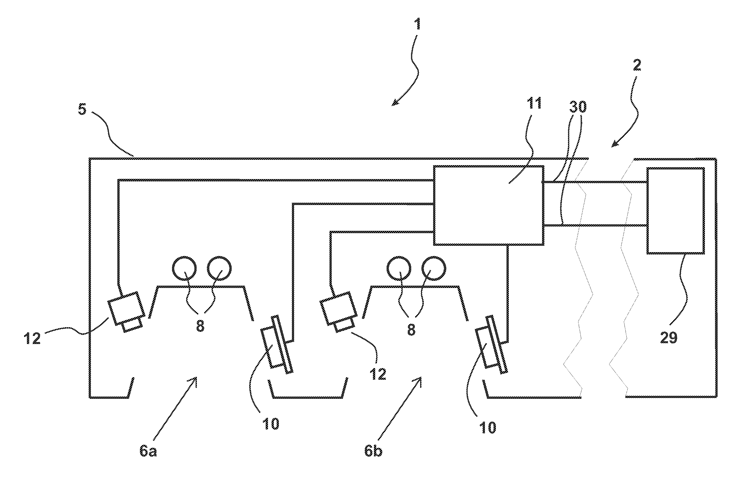
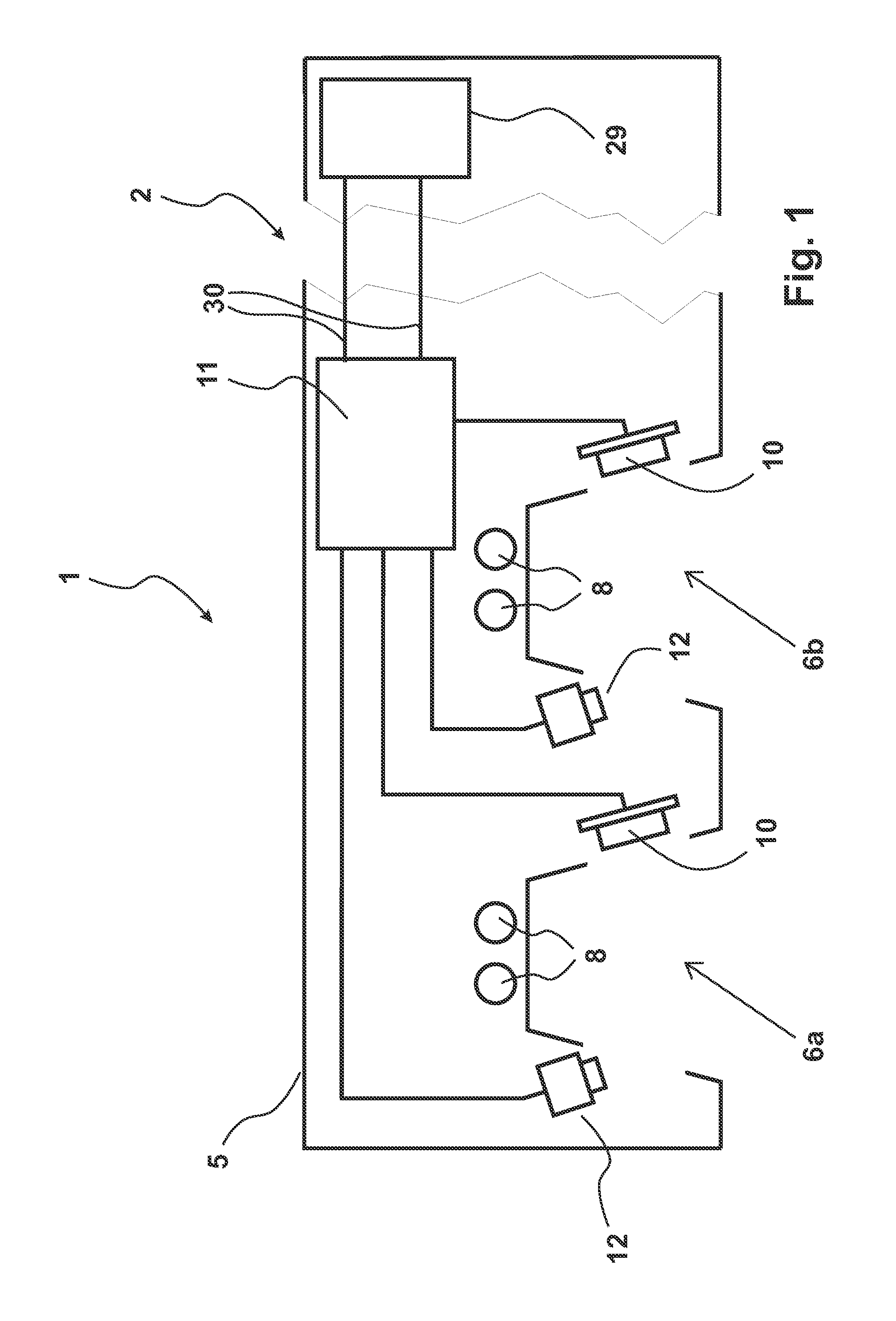
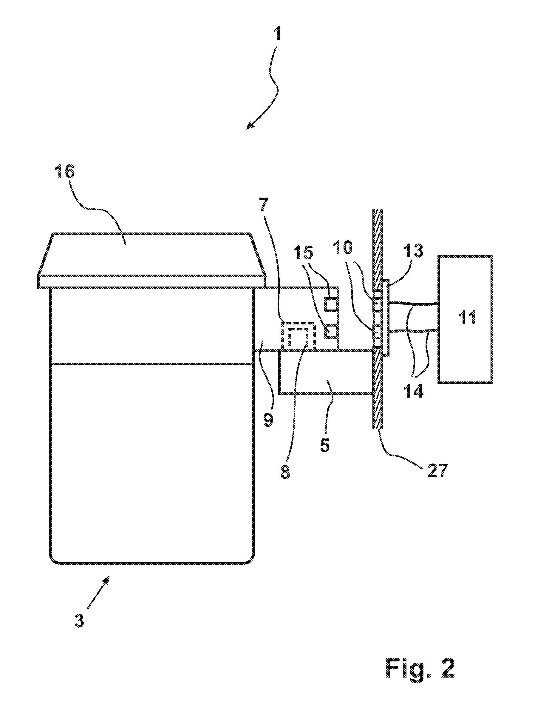
[0029]Referring to the drawings in particular, as was explained above, the anesthesia system 1 according to the present invention, which can be seen in FIGS. 1 and 2, comprises an anesthesia apparatus 2 and at least one anesthetic dispensing device 3, which is detachably coupled with the anesthesia apparatus 2 and which contains an anesthetic storage reservoir 4, in which anesthetic evaporates. The anesthesia apparatus 2 is provided with at least one mounting arm 5, which is shown in a cross-sectional view in the top part of FIG. 1. The exemplary mounting arm 5 is provided with two recesses 6a, 6b, which are designed to receive two dispensing devices 3. Mounting arm 5 is provided for this purpose with two holding pins 8 at each of the recesses 6a, 6b, which said holding pins 8 are used for being received in corresponding holes 7, which are formed in a bracket 9 of the dispensing device (shown in FIG. 2). The basic principle of this structure forms a fluid connection 7, 8 between the...


PUM


Abstract

An anesthesia system for providing a breathing gas enriched with anesthetic has an anesthesia apparatus (2) and at least one anesthetic dispensing device (3), which is detachably coupled with the anesthesia apparatus. A fluid connection (7, 8, 9) is provided between the anesthesia apparatus and the dispensing device, which is designed to send anesthetic from the dispensing device into the anesthesia apparatus. At least one optical interface is provided between the anesthesia apparatus and the dispensing device. At least one display device is provided in the dispensing device. The optical interface has at least one light source (10), which is provided in the anesthesia apparatus, and at least one fiber optic light guide (20), which is provided in the anesthetic dispensing device (3). The light fed by the light source (10) into the fiber optic light guide is sent to the display device to directly or indirectly light the display device.

Description

CROSS REFERENCE TO RELATED APPLICATIONS[0001]This application claims the benefit of priority under 35 U.S.C. §119 of German Patent Application DE 10 2010 022 828.1 filed Jun. 5, 2010, the entire contents of which are incorporated herein by reference.FIELD OF THE INVENTION[0002]The present invention pertains generally to an anesthesia system for providing a breathing gas enriched with anesthetic. The present invention pertains, in particular, to an anesthesia system, which comprises an anesthesia apparatus and at least one anesthetic dispensing device, which is detachably coupled with the anesthesia apparatus. The anesthetic dispensing device contains essentially an anesthetic reservoir, in which anesthetic evaporates and a dispensing means to set the concentration of the anesthetic. The coupling between the at least one anesthetic dispensing device and the anesthesia apparatus proper is designed to bring about a fluid connection between the anesthesia apparatus and the at least one ...

Claims


Application Information

Patent Timeline
Patent Type & Authority Applications(United States)
IPC IPC(8): A61M16/01
CPCA61M16/186A61M2205/18A61M2205/3389A61M2205/587A61M2205/584A61M2205/6063A61M2205/3386A61M2205/502
Inventor FABER, SONKERFALB, WOLFGANGHEIDSCHMIDT, MICHAELHEYER, SVENLUTTER, THOMASMARX, CORNELIAMEYER, MARTINPASDZIOR, SVENRADOMSKI, KLAUSSTARK, HARTMUT
Owner DRAGERWERK AG
Why Eureka
Try Eureka