
Pivot knuckle joint and tent using the same

a knuckle joint and pivoting technology, applied in the field of tents, can solve the problems of inconvenience in use, time-consuming and laborious set-up or disassembly process,

Inactive Publication Date: 2011-12-08
HENG GIN ENTERPRISE
View PDF4 Cites 25 Cited by
  • Summary
  • Abstract
  • Description
  • Claims
  • Application Information

AI Technical Summary

Benefits of technology

[0005]The primary object of the present invention is to provide a pivot knuckle joint, which is applicable to unfold support tubes connected to male and female joints to a predetermined clamping angle by controlling positioning of the male and female joints using a shaft rod, so as to present a secured status, and applicable to release the secured status of the support tubes by pushing and pressing the shaft rod, so as to fold the support tubes rapidly.
[0006]Another object of the present invention is to provide a pivot knuckle joint, wherein male and female joints are connected to a support tube of a tent respectively. When the support tubes are unfolded, a stopper portion of a shaft rod is inserted into the male and female joints to secure an unfolded status of the support tubes. When the support tubes are folded, a pressing member is pressed to enable the stopper portion of the shaft rod to slide out of the male and female joints, so as to rotate the male and female joints to fold the support tubes. Thus, the tent is set up or folded rapidly.
[0008]In order to achieve the aforementioned object, the raised access floor unit according to the present invention comprises a frame member and a block member, the frame member has a receiving space for raw materials of the block member to be poured and harden inside the receiving space, characterized in that the bottom of the frame member is disposed with a plurality of T-shaped plate members, wherein the plurality of T-shaped plate members are formed directly from the bottom of the frame member so as to dispose the plurality of T-shaped plate members into the block member while the raw materials of the block member are poured to the frame member, thereby allowing the block member to be incorporated into the frame member securely.

Problems solved by technology

However, the above set-up and disassembly steps in the modes of setting up the tent are complicated, the set-up or disassembly process is time-consuming and labor-consuming, or even many people are needed to work together at the same time.
What's worse, the tent may often collapse as the camping ropes become loosened, thereby causing inconveniences in use.

Method used


Image

  • Pivot knuckle joint and tent using the same
  • Pivot knuckle joint and tent using the same
  • Pivot knuckle joint and tent using the same

Examples


Embodiment Construction

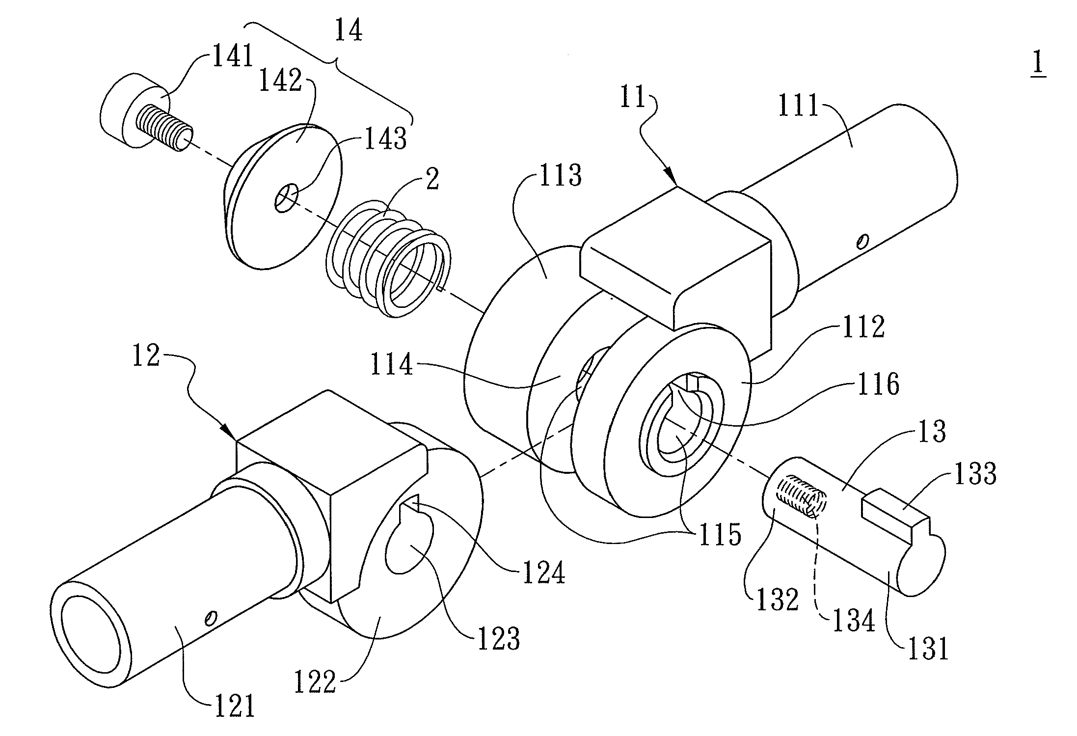
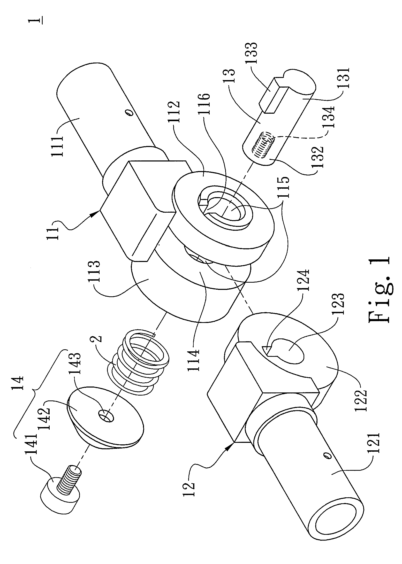
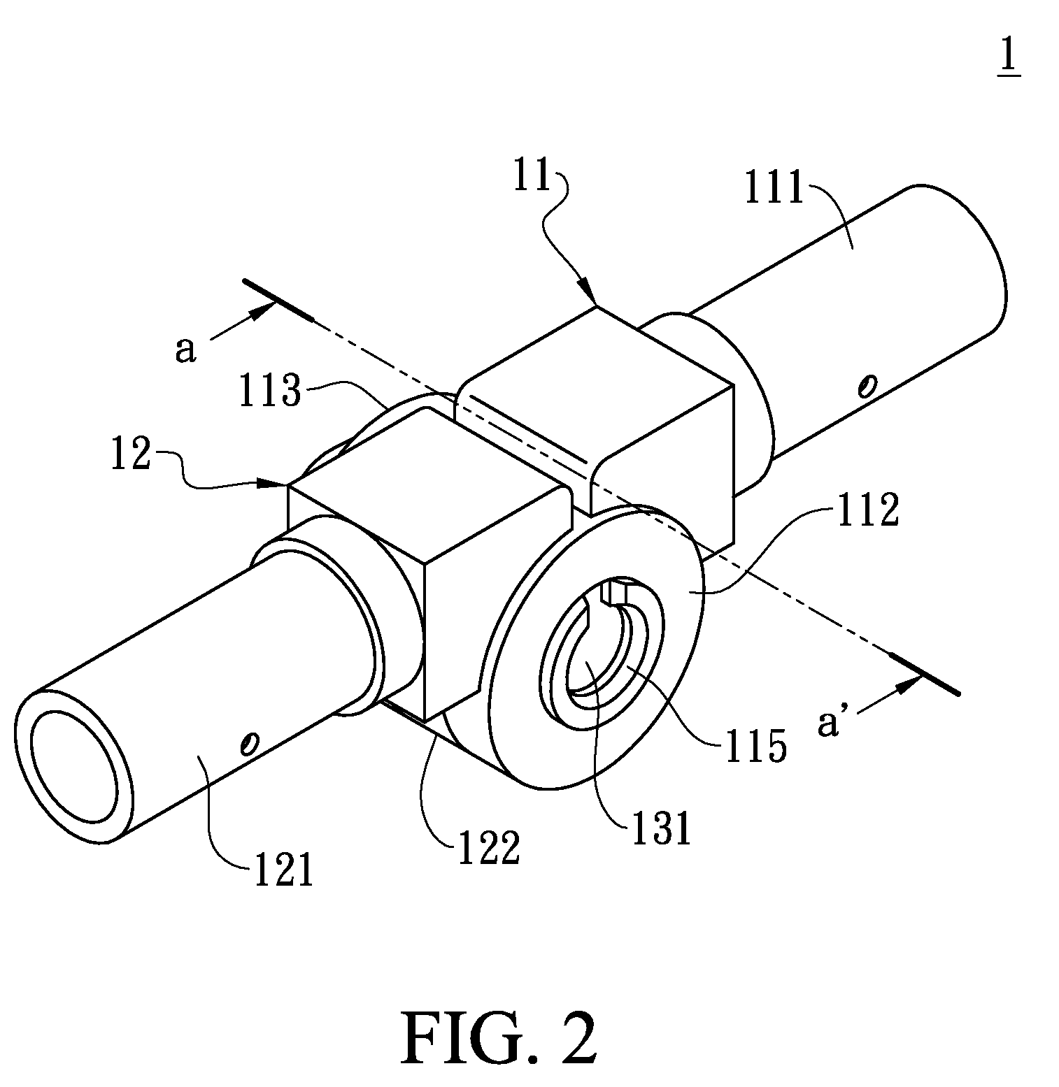
[0026]FIG. 1 shows a pivot knuckle joint 1 according to a first embodiment of the present invention. The pivot knuckle joint 1 includes a female joint 11, a male joint 12, a shaft rod 13, and a pressing member 14.

[0027]A junction portion 111 for being joined with a support tube of a tent is disposed at one end of the female joint 11, and a first shaft disk 112 and a second shaft disk 113 having a round shape are disposed at the other end of the female joint 11, so that an accommodation space 114 is formed at an inner side of the first and second shaft disks (112 and 113) of the female joint. A shaft hole 115 is opened at a center of the first and second shaft disks (112 and 113) respectively, and a sliding slot 116 is provided at a periphery of the shaft hole 115 of the first shaft disk 112. Moreover, an accommodation slot 117 is provided at an outer side of the second shaft disk 113 (as shown in FIG. 3).

[0028]A junction portion 121 for being joined with a support tube of a tent is ...


PUM


Abstract

A pivot knuckle joint and a tent using the same are provided. The pivot knuckle joint includes a male joint and a female joint. A junction portion for being joined with a support tube is disposed at one end of the male joint and a pivot plate is disposed at the other end of the male joint. A shaft hole is opened on the pivot plate. A junction portion for being joined with a support tube is disposed at one end of the female joint and a first shaft disk and a second shaft disk are disposed at the other end of the female joint. A shaft hole is opened on the first and second shaft disks respectively. An accommodation space is formed at an inner side of the first and second shaft disks. When the pivot plate of the male joint is inserted into the accommodation space, a shaft rod penetrates through shaft holes of the male and female joints, so as to control a positioning status of the male and female joints, thereby unfolding or folding the tent rapidly.

Description

FIELD OF THE INVENTION[0001]The present invention relates to a tent, and more particularly to a tent capable of being unfolded or folded rapidly by using pivot knuckle joints.DESCRIPTION OF THE PRIOR ART[0002]As people have paid more and more attention to leisure life outdoors, camping becomes a popular activity to enjoy the nature. A tent is an indispensable outfit for the camping activity, which provides a temporary shelter. The commercially available tents, especially light and portable ones that can be easily set up or disassembled are very popular among users.[0003]In a conventional mode of setting up a tent, a plurality of support tubes penetrates into sleeve tubes on the tent cloth, and then is inserted into pedestals at a periphery of the tent, so that the support tubes are secured. In another common mode of setting up a tent, a plurality of single-section support tubes is assembled into long rods to support the tent cloth, and the long rods and the tent cloth are secured on...

Claims


Application Information

Patent Timeline
Patent Type & Authority Applications(United States)
IPC IPC(8): F16C11/04E04H15/48
CPCE04H15/42Y10T403/32557E04H15/48
Inventor CHEN, YI-MING
Owner HENG GIN ENTERPRISE
Learn More