Battery mounting structure of electromotive vehicle
- Summary
- Abstract
- Description
- Claims
- Application Information
AI Technical Summary
Benefits of technology
Problems solved by technology
Method used
Image
Examples
Embodiment Construction
[0037]Hereafter, a preferred embodiment of the present invention will be descried.
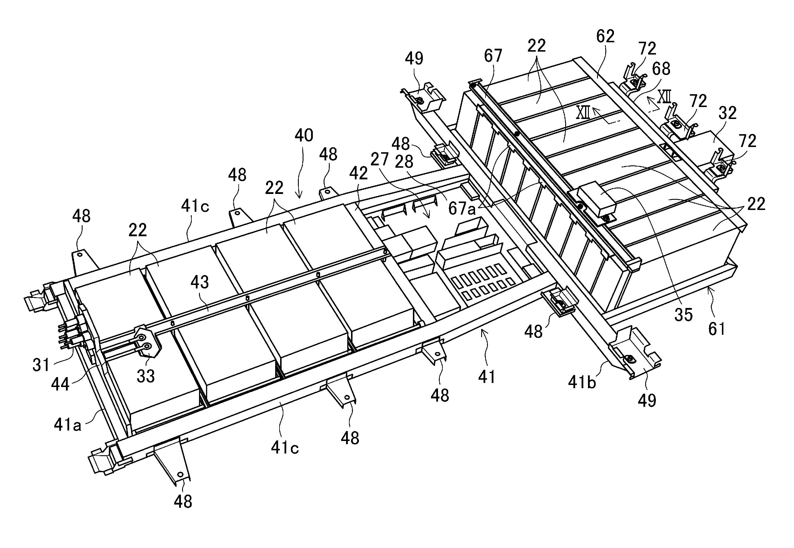
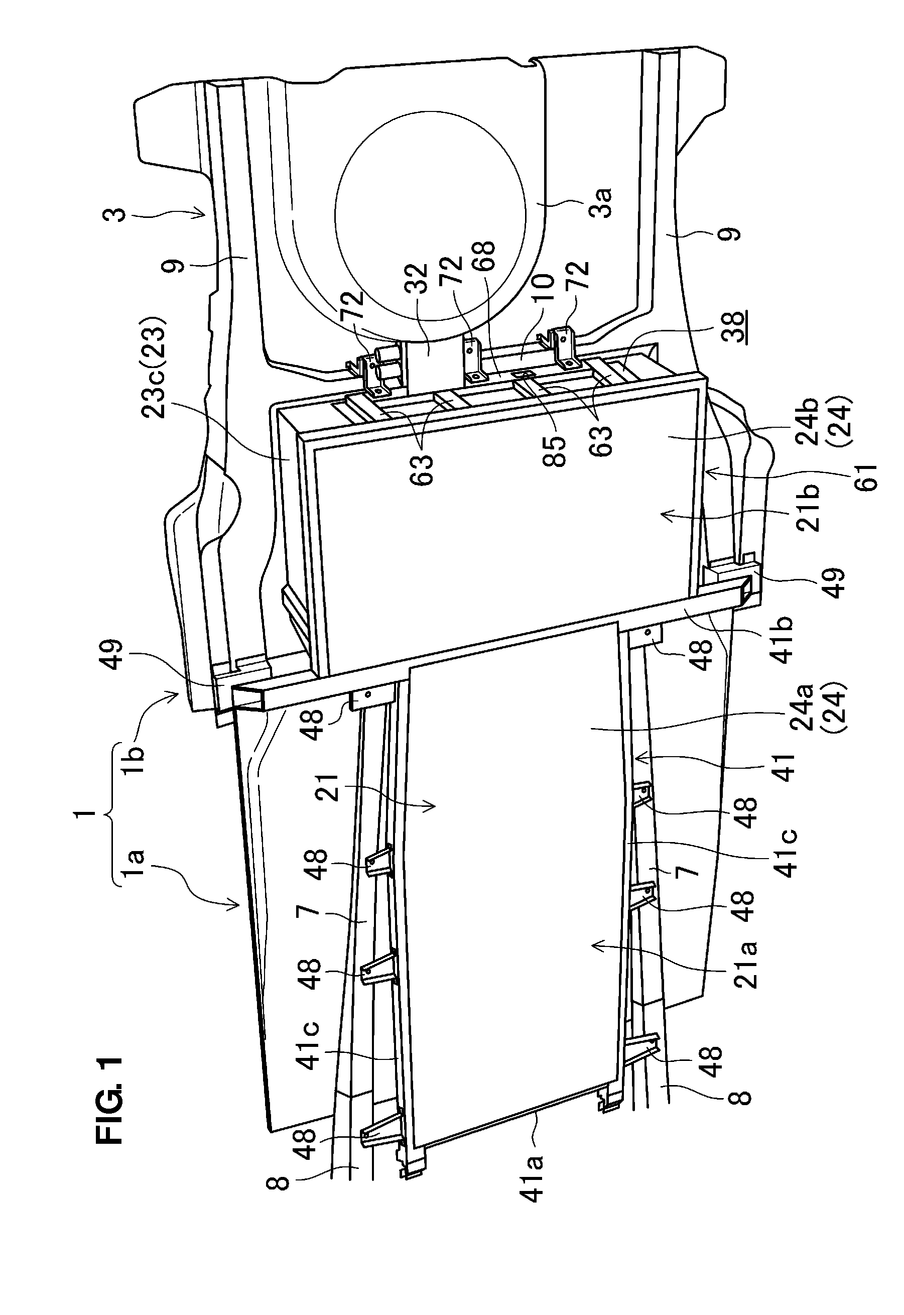
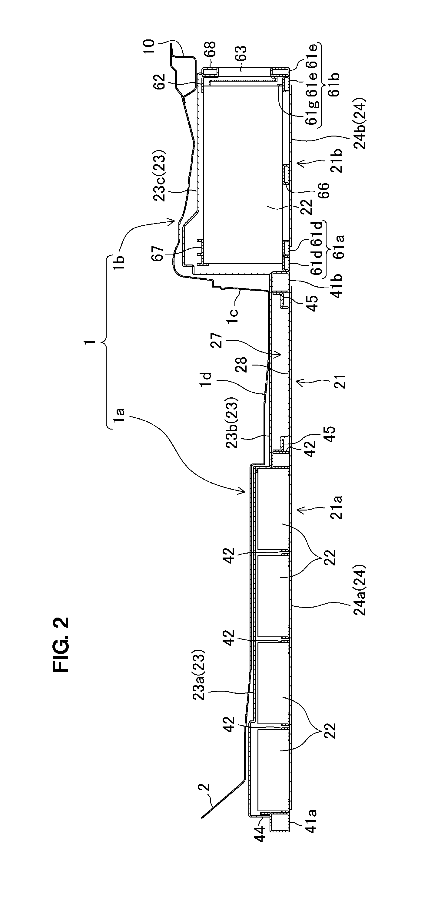
[0038]FIGS. 1 and 2 show a lower-side vehicle floor 1 of an electromotive vehicle (an electric vehicle in the present embodiment) which is equipped with a battery mount structure according to the present embodiment of the present invention. Herein, the front, rear, left, right, above, or below with respect to a vehicle will be simply referred to as the “front”“rear”“left”“right”“above” or “below.”
[0039]The vehicle floor 1 comprises a front floor portion 1a and a rear floor portion 1b which is located above the level of the front floor portion 1a. That is, a kick-up portion 1c is formed between the front floor portion 1a and the rear floor portion 1b, and the level of the rear floor portion 1b is higher than the front floor portion 1a by the height of this kick-up portion 1c.
[0040]A rear seat (not illustrated) is arranged on the rear floor portion 1b. A foot place 1d for a passenger seated in the rear ...
PUM
 Abstract
Description
Claims
Application Information
 - R&D
- Intellectual Property
- Life Sciences
- Materials
- Tech Scout
- Unparalleled Data Quality
- Higher Quality Content
- 60% Fewer Hallucinations
Browse by: Latest US Patents, China's latest patents, Technical Efficacy Thesaurus, Application Domain, Technology Topic, Popular Technical Reports.
© 2025 PatSnap. All rights reserved.Legal|Privacy policy|Modern Slavery Act Transparency Statement|Sitemap|About US| Contact US: help@patsnap.com


