Scanning device

Inactive Publication Date: 2011-12-08
CAL COMP ELECTRONICS +1
View PDF7 Cites 4 Cited by
  • Summary
  • Abstract
  • Description
  • Claims
  • Application Information

AI Technical Summary

Benefits of technology

[0007]The present disclosure is directed to a scanning device, and a chance o

Problems solved by technology

However, during a moving process of the scanning head, the scanning head can be swayed due

Method used


Image

  • Scanning device
  • Scanning device
  • Scanning device

Examples


Embodiment Construction

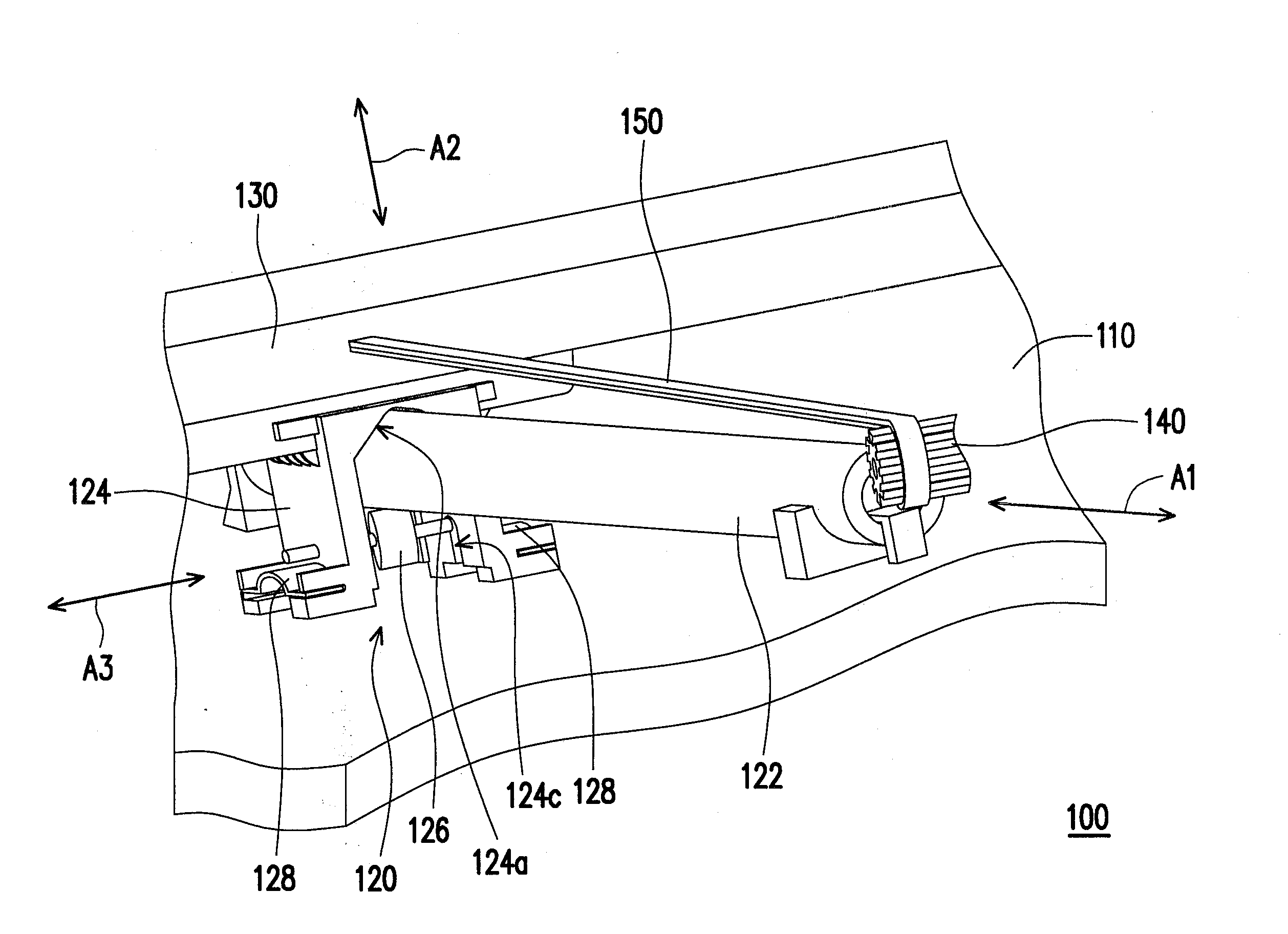
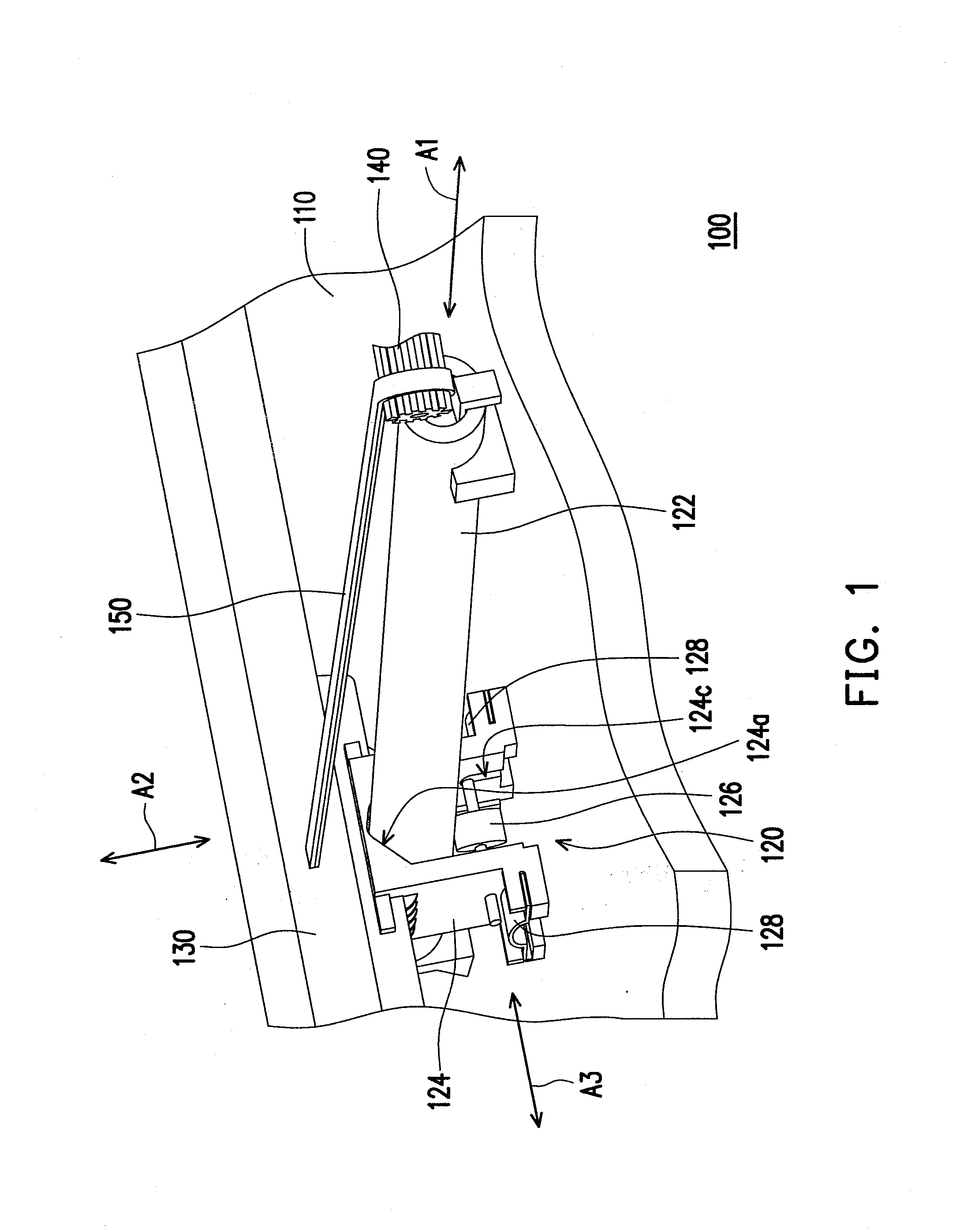
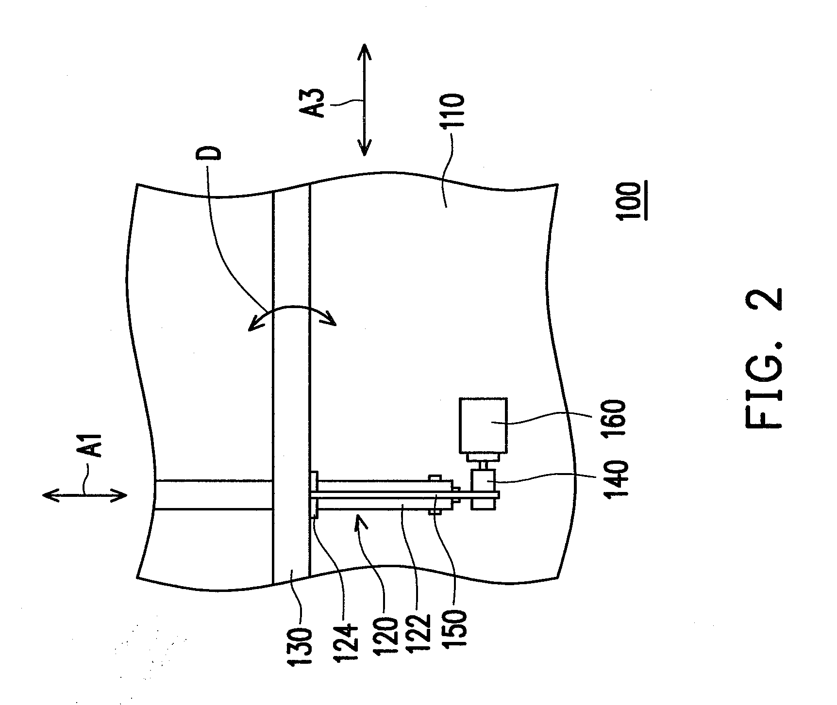
[0022]FIG. 1 is a partial three-dimensional view of a scanning device according to an exemplary embodiment of the disclosure. FIG. 2 is a top view of the scanning device of FIG. 1. Referring to FIG. 1, the scanning device 100 includes a base 110, a guiding module 120 and a scanning head 130. The guiding module 120 includes a guiding rod 122, a guiding element 124, a sliding element 126 and elastic elements 128 (two elastic elements are illustrated). The guiding rod 122 is fixed to the base 110. The guiding element 124 has a notch 124a, wherein the guiding rod 122 is slidingly disposed at the notch 124a along a first axial direction A1. The scanning head 130 is fixed to the guiding element 124, so as to perform scanning following the movement of the guiding element 124 along the guiding rod 122 along the first axial direction A1.

[0023]FIG. 3 is a partial front view of the scanning device of FIG. 1. Referring to FIG. 3, the sliding element 126 is slidingly disposed at the guiding elem...


PUM


Abstract

A scanning device including a base, a guiding module and a scanning head is provided. The guiding module includes a guiding rod, a guiding element, a sliding element and an elastic element. The guiding rod is fixed to the base. The guiding element has a notch, wherein the guiding rod is slidingly disposed at the notch along a first axial direction. The sliding element is slidingly disposed at the guiding element along a second axial direction substantially perpendicular to the first axial direction. The elastic element is fixed to the guiding element and contacts with the sliding element, wherein the sliding element pushes the guiding rod to contact an inner wall of the notch along the second axial direction by an elastic force of the elastic element, so as to prevent the guiding rod from swaying during a scanning process.

Description

CROSS-REFERENCE TO RELATED APPLICATION[0001]This application claims the priority benefit of Taiwan application serial no. 99118190, filed on Jun. 4, 2010. The entirety of the above-mentioned patent application is hereby incorporated by reference herein and made a part of specification.BACKGROUND[0002]1. Field of the Disclosure[0003]The present disclosure relates to an image capturing device. More particularly, the present disclosure relates to a scanning device.[0004]2. Description of Related Art[0005]Recently, with a rapid development of computer technology, and a price of scanning devices goes down because of a strong market competition, the scanning devices become very popular computer peripherals in the market.[0006]The scanning devices can be grouped into a plurality of patterns according to prices and functions thereof. In detail, the scanning devices can be grouped into handheld scanning devices, sheet-fed scanning devices, business card scanning devices, film scanning device...

Claims


Application Information

Patent Timeline
IPC IPC(8): H04N1/04
CPCH04N1/1017H04N1/1026H04N2201/0442H04N1/193H04N2201/0081H04N1/103
Inventor WANG, CHIH-HWA
Owner CAL COMP ELECTRONICS
Why Eureka
Try Eureka